Downloads
Download


This work is licensed under a Creative Commons Attribution 4.0 International License.
Article
Joint Calibration of MIMO Radar Arrays under Multiple Signal Sources
Bin Wang 1, Xiaoyu Xie 1, and Shufei Yin 1,2,*
1 Shanghai Baolong Automotive Corporation, Shanghai 201619, China
2 School of Automotive Engineering, Wuhan University of Technology, Wuhan 430070, China
* Correspondence: yinshufei@chinabaolong.net
Received: 7 October 2023
Accepted: 2 November 2023
Published: 6 December 2023
Abstract: The 4D vehicle-mounted millimeter-wave radar can simultaneously measure the horizontal and vertical angles, which depends on the arrangement of the multiple-input multiple-output (MIMO) array antenna. In practical engineering applications, to ensure the calculation accuracy of horizontal angle and vertical angle, it is necessary to calibrate the array phase error and array antenna spacing error. In this paper, aiming at the simultaneous occurrence of array amplitude-phase errors and array antenna spacing errors, a mathematical model of MIMO antenna array errors is established. At the same time, the impact of array errors is analyzed by simulation. An array joint calibration method under multi-source is proposed, and the proposed calibration method is simulated and analyzed. The results show that the array phase error and the array spacing error can be calibrated at the same time through this calibration method, which can meet the calibration requirements in the mass production process of vehicle radar. The calibration method mentioned in this paper has the advantages of simplicity and high efficiency for the calibration of vehicle radar at this stage.
Keywords:
4D vehicle-mounted millimeter-wave radar multiple-input multiple-output (MIMO) angle of arrival estimation array amplitude-phase error array spacing error1. Introduction
4D millimeter-wave radar has the capability of measuring the distance, speed, azimuth, and vertical angle of the target. Compared with the traditional millimeter-wave radar, it has the new function of measuring the vertical angle, and has an extended detection range of distance, a higher resolution in distance and speed. The characteristics of angular resolution can output higher quality point cloud data. Compared with other vehicle-mounted sensors, millimeter-wave radar has the advantages of operating in all-day and all-weather conditions and maintains good performance in a variety of severe weather environments. Because of these advantages, 4D millimeter-wave radar can support high-level autonomous driving applications like L3, when combined with a variety of processing technique like deep learning. These techniques can improve the performance of automotive radar in real-world complex driving scenarios [1]. The 4D millimeter-wave radar has become an indispensable sensor in the Advantage Driving Assistance System and in the automatic driving system [2].
To adapt to practical applications, much research has focused on improving the reliability of 4D radar data. For example, efforts have been made to improve the dynamic range of radar target detection, and to make the moving detection target stable [3]. Additionally, improvements have been conducted in the angular resolution of radar to capture more abundant target information [4‒6]. More complex waveform designs have been employed to enhance the anti-interference ability [7,8]. Advanced frontier antenna designs like waveguide antenna have been utilized [9,10]. Algorithms have been developed to address the challenges such as multipath selection [11], the calibration associated with radar installation on vehicles, the detection errors occurred when radar covered by snow or mud, and the hardware process-induced detection errors.
The high angular resolution and angular accuracy of millimeter-wave radar typically depend on the arrangement and calibration of multiple-input multiple-output (MIMO) antenna arrays. In practical engineering, the sources of angle measurement errors of MIMO array antenna include array amplitude-phase errors and array spacing errors. The array amplitude-phase errors represent a complex gain error independent of azimuth, which is usually caused by the inconsistent gain of the amplifier in the receiving channel and the variations of the component parameters in each channel. The array spacing errors typically result from the manufacturing process, which causes the discrepancies between the arrays and the design errors. When spacing errors exist, they can be equivalent to the introduction of azimuth-dependent phase perturbation into the steering vector of the array.
The influence of array errors on angle estimation is analyzed in reference [12,13]. After the least square fitting calibration of the source’s steering vector as discussed in reference [14], it can be applied to any angle estimation algorithm. In literatures [15,16], the known information source is combined with the maximum likelihood method to estimate both the array amplitude-phase error and the array element position error. However, this method requires a large amount of calculation in the multi-dimensional search process, and the algorithm is more complex. In reference [17], the Instrumental Sensors Method (ISM) auxiliary array element algorithm is proposed. Although this algorithm can be used for any array structure, it requires the error information of the auxiliary array element to be accurately known. When the error information of the accurately calibrated auxiliary array element changes or the accurate error cannot be obtained, the calibration effectiveness of the auxiliary array element method will deteriorate. At the same time, this method requires the number of auxiliary array elements to exceed the number of sources.
This paper first analyzes the angle estimation process of the vehicle-mounted millimeter-wave radar, and then gives the model of signal error and angle estimation spectrum analysis through theoretical analysis. At the same time, a joint calibration algorithm suitable for array amplitude-phase and array spacing of vehicle-mounted millimeter-wave radar is proposed. Finally, the influence of amplitude-phase errors and array spacing errors on the angle estimation spectrum is analyzed. Then the results of the angle estimation spectrum after the joint calibration method are given, and the calibration performance is evaluated by simulation.
The structure of the article is as follows. The second section introduces the angle estimation process and error model of vehicle-mounted millimeter-wave radar, and then introduces the theory of joint calibration algorithm. The third section analyzes and compares the simulation results before and after calibration. The fourth section discusses the research of this paper. The fifth section provides a summary.
2. Methods
This chapter first introduces the common system structure of 4D vehicle-mounted millimeter-wave radar system at present, and briefly describes the signal processing flow of radar ranging, velocity measurement and angle measurement. Then, the signal model of angle measurement of 4D radar is described in detail, and the importance of radar calibration to angle measurement is explained. Finally, a new array joint calibration method is given.
2.1. Radar System
The main structures and signal processing of the 4D vehicle-mounted millimeter-wave radar system at this stage are shown in Figure 1. The voltage that changes linearly with time is generated inside the radar chip. After passing through the Phase Locked Loop (PLL), a frequency modulation signal in which frequency changes linearly with time, referred to as a chirp, is generated. The linear frequency modulation signal is multiplied by the Local Oscillator (LO) module to generate a linear frequency modulation signal with a center frequency of 77 GHz, and then fed out by the Radio Frequency (RF) front-end module Monolithic Microwave Integrated Circuit (MMIC) through the phase shifter. MIMO antenna is typically used in the RF front-end of vehicle millimeter-wave radar. The use of MIMO antenna can maximize the utilization of space resources, increase channel capacity and transmission efficiency. After the electromagnetic wave signal reaches the target, it is reflected to generate an echo signal, received by the receiving antenna. After mixing, an Intermediate Frequency (IF) signal is generated. The intermediate frequency signal is sampled by the Analog-to-Digital Converter (ADC) to obtain the required data called ADCRawData. The data of ADCRawData can be represented by the cube shown in Figure 1. The Fast Time direction is also called the distance dimension, and the Slow Time direction is also called the speed dimension. The Transmit and Receive (T/R) channel refers to the information channel corresponding to the MIMO antenna [18].
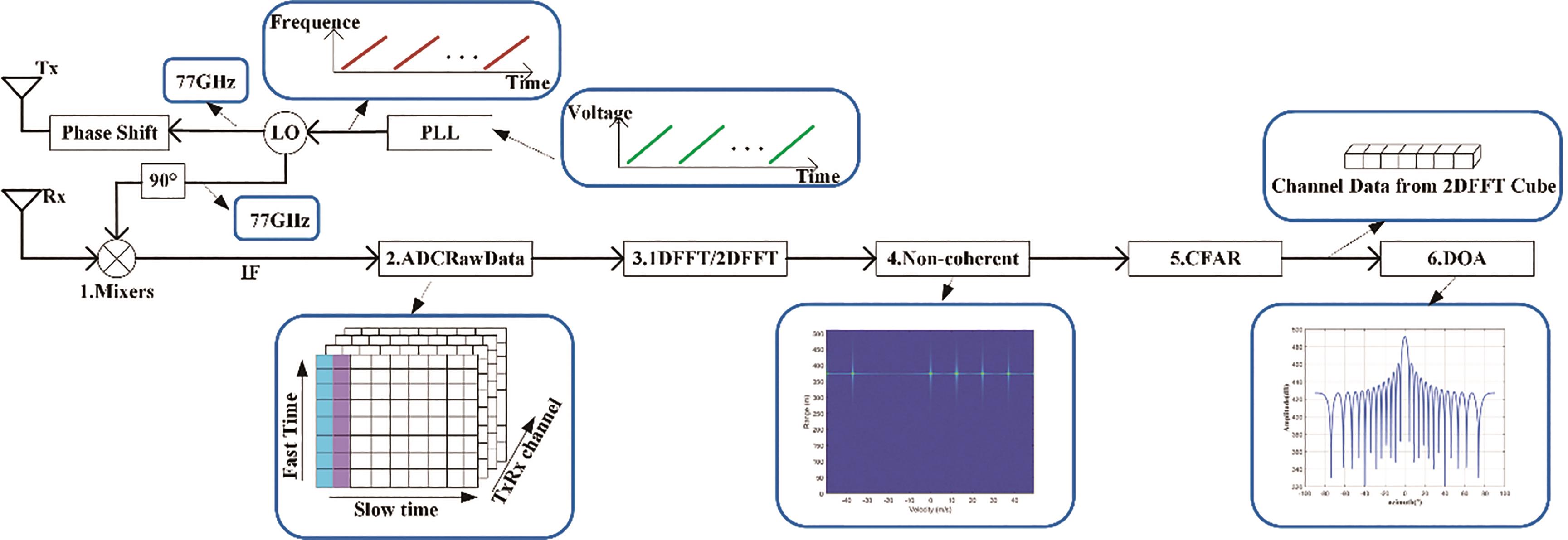
Figure 1. 4D millimeter-wave radar system and signal processing.
In the radar chip, ADCRawData uses the hardware accelerator inside the chip to perform 1DFFT on the Fast Time dimension data, and then performs 2DFFT on the Slow Time dimension data to obtain the RadarCube data. The RadarCube data is processed by non-coherent accumulation to obtain a dataset called RDMap. Since the Doppler Diversity Multiple Access (DDMA) waveform is used in [19], the same target on the RDMap will be separated on the slow time dimension [19]. Constant False Alarm Rate (CFAR) detection is performed on RDMap data. At this time, the distance and speed information of the target can be obtained. The target index detected by CFAR detector can be traced back to the data RadarCube obtained by the 2DFFT, to obtain the data of the T/R channel corresponding to the target, which is also known as snapshot data. By estimating the angle of arrival of the snapshot data, the angle of the target is obtained [20]. Finally, the (X, Y, Z) position of the target in the three-dimensional coordinates is output, and the radar signal processing is completed.
2.2. Signal Model
As shown in Figure 2, the equivalent array of the radar is arranged on the ZOX axis to form a planar array. The total number of sources is  , and
, and  ,
,  represent the azimuth and elevation angles of the ith source (
  ), respectively. The array signal model can be expressed as follows:

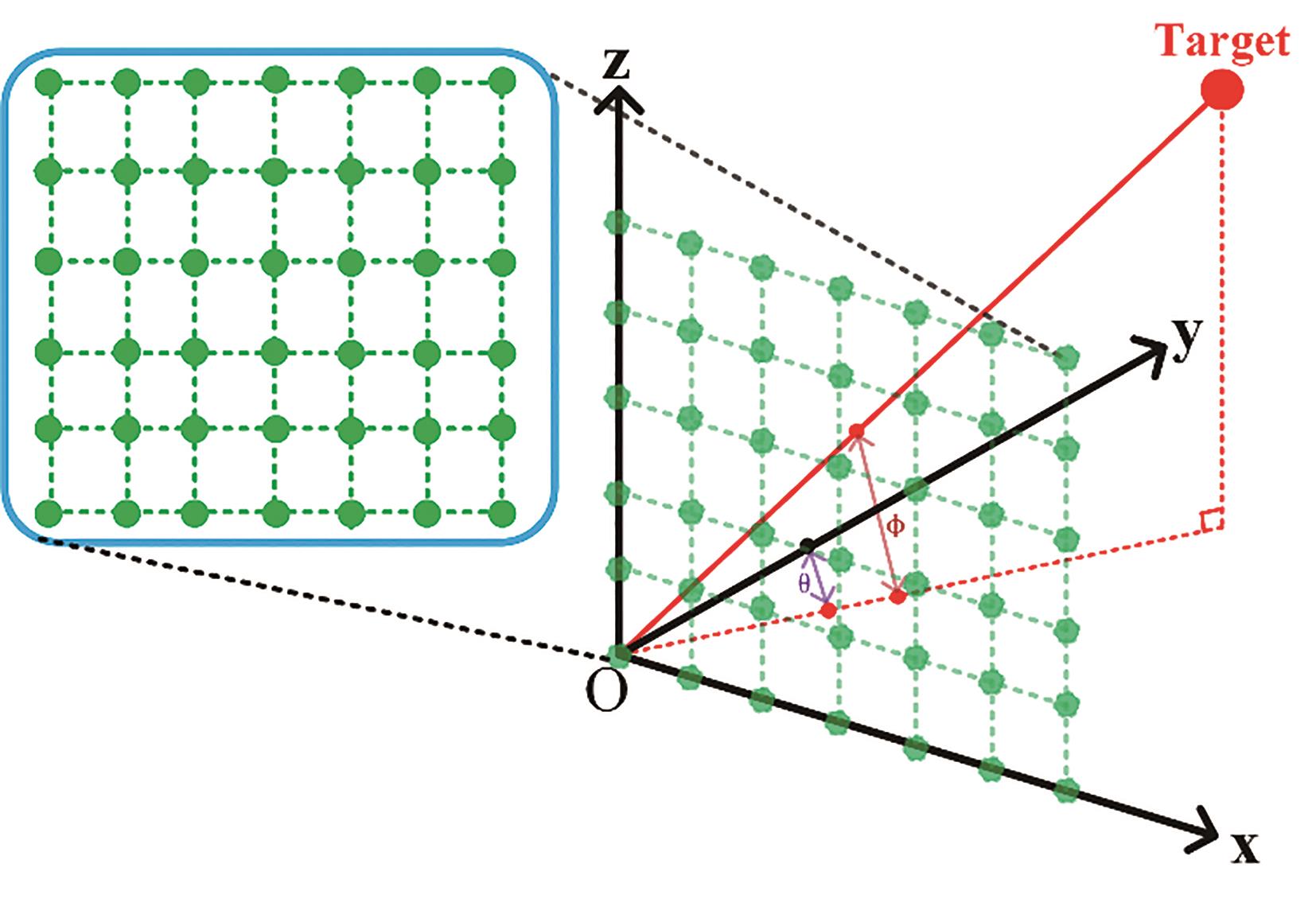
Figure 2. Array angle measurement diagram.
where


 and
and  represent the output signal of the antenna array element and the additive noise of the array element, respectively. The dimension is
  , indicating that there are
  array elements.
  represents the signal corresponding to the echo after mixing, and the dimension is
  , which means that there are
  targets in the space.

where  is
is  order matrix, and each column is denoted by
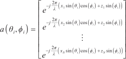
where  denotes the direction of the source wave
  , and the phase change corresponding to each element after the arrival of the wave to
  elements, also known as the steering vector;
  represents the wavelength.
  is related to the position
  of the array element in the coordinate and the direction
  of the target wave, and
  is called the array manifold.
When the array has both amplitude-phase error and array position spacing error,  can be expressed as follows:

The former vector of Equation (7) represents the total error of  ,
,  represents the amplitude error, and the phase error in the amplitude-phase error can be added to the array element spacing error represented by
  ,
,  . The array calibration is the first error vector in calibration Equation (7).
2.3. Calibration Methods
We often select an array element as the reference array element point and set the reference array element point to 0 point of the coordinate axis.  can be obtained by normalizing the steering vector value corresponding to the first array element by Equations (7) and (8).

For Equation (1), array data covariance can be expressed as follows:

where  is a subspace spanned by eigenvectors corresponding to large eigenvalues, also known as signal subspace;
  represents the subspace spanned by the remaining feature vectors, also known as the noise subspace. Under ideal conditions, the signal subspace and the noise subspace in the data space are orthogonal to each other. The space spanned by the eigenvector corresponding to the large eigenvalue in the covariance matrix is the same space spanned by the steering vector of the incident signal [21], that is, the steering vector
  in the signal subspace is also orthogonal to the noise subspace. The relationship is shown in Equation (10).

When there is an error in the array element position, the steering vector of the array can be approximated as:

where  is the steering vector under the ideal array spacing,
  and
and  are the first-order partial derivatives in the
  and
and  directions, respectively. For
  can be expressed as
  ,
,  is shown in Equations (12) and (13).


Also, for  can be expressed as
  ,
,  as shown in Equations (14) and (15).


Substituting Equation (11) into Equation (10), Equation (10) is also denoted by

where Equation (16) can be changed into as follows:

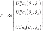


where the dimension of  is
is  , the dimension of
  is
is  , and the dimension of
  is
is  .
.
According to the projection theorem, when Equation (17) takes the minimum, we have

 is the spacing error of array elements.
After obtaining the spacing error, according to Equation (8), the amplitude error can be obtained as
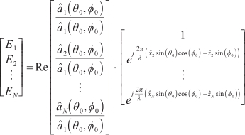
where  is the angle of the signal source,
  and
and  represent the calibrated array spacing, and
  represents the feature vector corresponding to the signal subspace. There may also be errors in the amplitude at different angles. It is necessary to average the amplitude errors under multiple sources and replace the amplitude errors in all directions with the average amplitude errors.
From the above, for the calibration of the array, it is necessary to have three signal sources with the same distance and the same speed at different angles to solve the array element spacing error in the  and
and  directions. For a single-dimensional uniform linear array, two signal sources with the same distance and the same speed at different angles are needed to solve the element spacing error in the single-dimensional direction. For the 4D vehicle-mounted millimeter-wave radar, due to the limitation of the computational complexity of the radar chip, the two-dimensional joint angle estimation is usually not carried out, but the single-dimensional angle estimation is carried out in the horizontal and pitch directions respectively, and then the angle matching and decoupling are carried out. Therefore, the calibration can choose to perform single-dimensional linear array calibration in the horizontal and pitch directions respectively, so that only two sources with the same distance and the same speed at different angles can be used for calibration.
3. Results
To evaluate the influence of amplitude error and array element spacing error, the simulation first establishes two far-field sources with the same distance and speed but different angles. In the signal processing flow of 4D vehicle-mounted millimeter-wave radar, the two targets will fall into the same distance index and speed index, and the two sources will be separated in the angle dimension. The equivalent array is a uniform array with 20 array elements, the array element spacing is half wavelength, and the number of snapshots is 50. The angles of the two targets to be measured are 15° and 20°, respectively. Gaussian white noise is added, and the Signal to Noise Ratio (SNR) is 10 dB.
For the case where only amplitude error occurs, a random distribution value with a mean value of 0 and a variance of 0.05 is added to the signal as the amplitude error. The simulation results are shown in Figure 3.
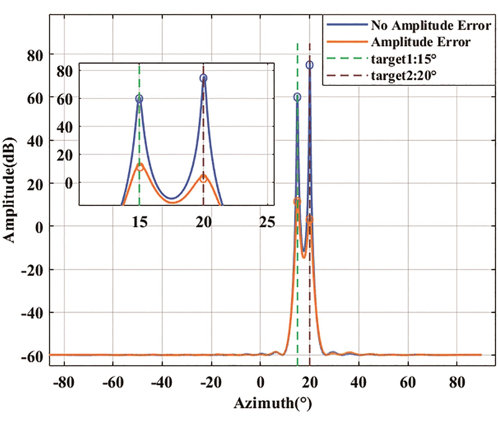
Figure 3. The influence of amplitude error on angle estimation spectrum.
It can be seen from Figure 3 that when the amplitude error occurs in the array, the peak value of the spectral peak decreases and the spectral peak is obviously broadened, and the resolution decreases, but the angle measurement is still accurate. The amplitude error only causes the decrease of the spectral peak resolution and has no effects on the angle measurement accuracy.
For the case where only phase error occurs, a random error with a mean value of 0 and a variance of 0.5 is added to the array element spacing. The simulation results are shown in Figure 4.
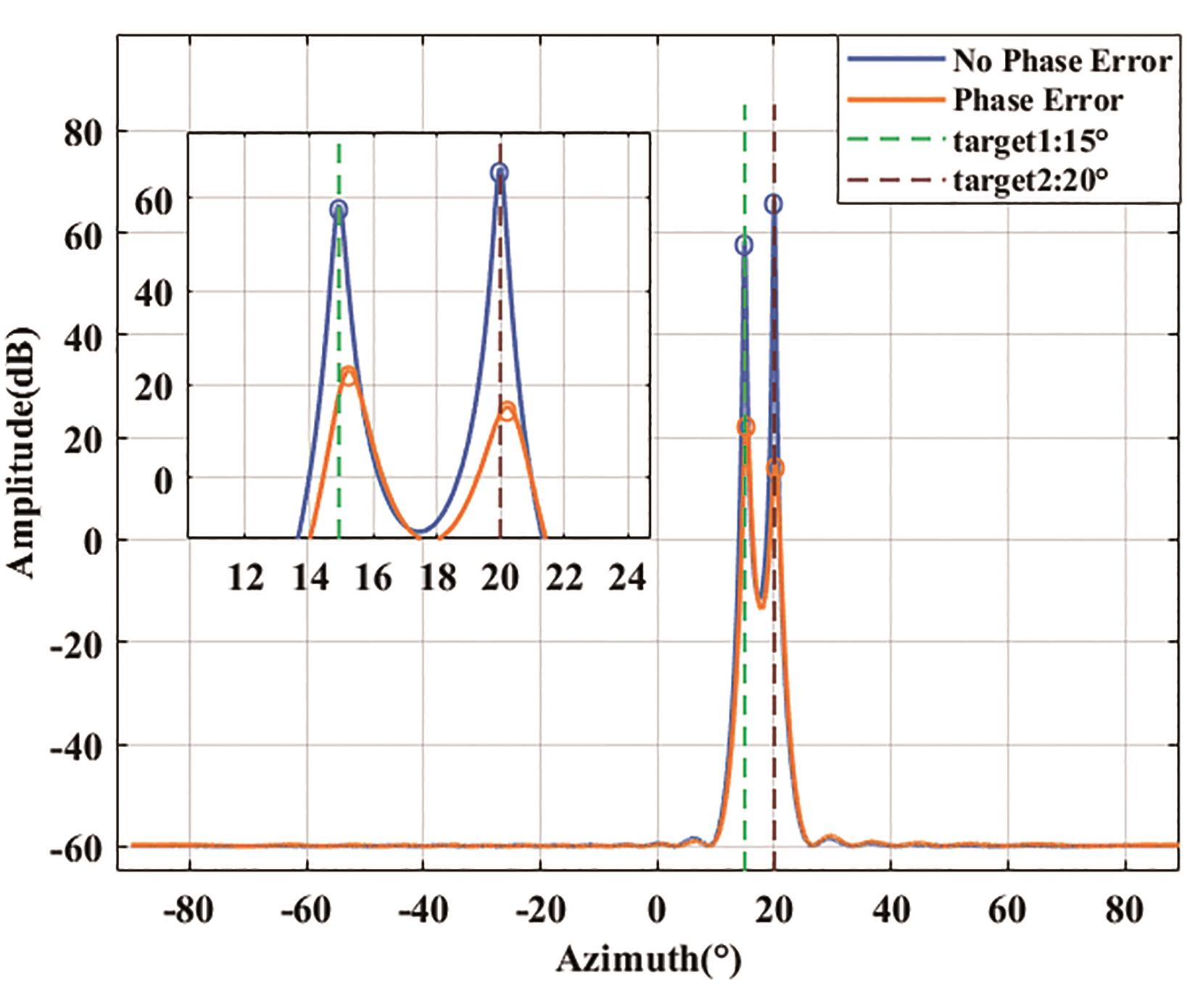
Figure 4. The influence of phase error on angle estimation spectrum.
It can be seen from Figure 4 that when the phase error occurs in the array, the spectral peak amplitude will decrease, the spectral peak value will obviously deviate from the actual angle of the source, and the spectral peak resolution will decrease but not obvious.
The amplitude error will affect the resolution of the spectral peak, and the phase error will affect the final angle estimation. The amplitude error and phase error are added to the array at the same time, and then the proposed joint calibration method is used to set the angle of the auxiliary calibration source to -6° and 10°. After calibration, a new array manifold is obtained, and then the 15° and 20° sources with random errors are added. The angle spectrum estimation after calibration is performed, and the results are shown in Figure 5.
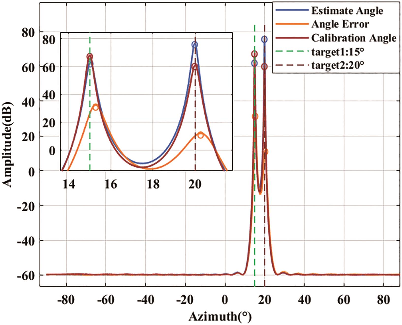
Figure 5. Angle estimation spectrum after joint calibration.
It can be seen from Figure 5 that the angle estimation spectrum after calibration has been significantly improved. In the case of angle estimation deviation and resolution reduction, the angle estimation after calibration is correct, and the resolution is close to the angle estimation spectrum without error, which proves the effectiveness of the method proposed in this paper.
At the same time, to analyze the influence of the signal-to-noise ratio of the auxiliary source on the final calibration result, 500 Monte Carlo simulation experiments are used to analyze under different SNR. The relationship between the mean and variance of the array element spacing error before and after calibration and the SNR is shown in Figure 6; the relationship between the mean value, variance, and SNR of the output angle before and after calibration is shown in Figure 7.
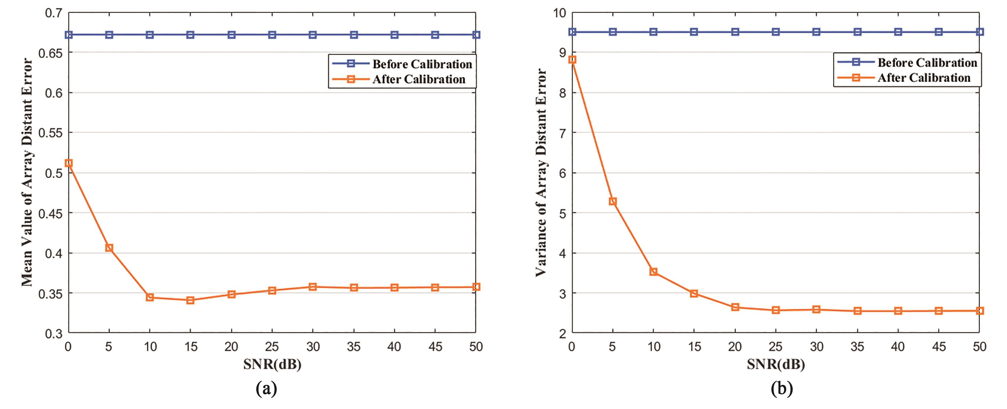
Figure 6. (a) Relationship between mean of array element spacing error and Signal to Noise Ratio (SNR); (b) Relationship between variance of array element spacing error and SNR.
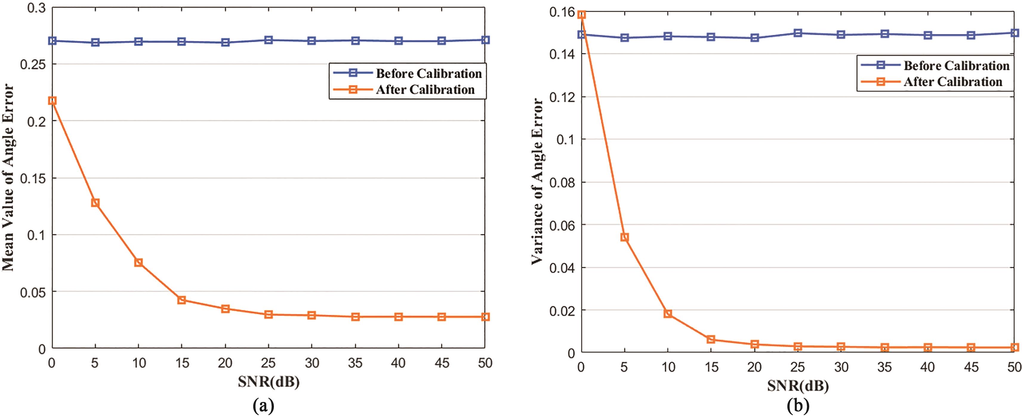
Figure 7. (a) Relationship between mean of angle estimation error and SNR; (b) Relationship between variance of angle estimation error and SNR.
It can be seen from Figure 6 that with the increase of the SNR of the auxiliary source, the mean value of the array element spacing error decreases continuously and the variance tends to a fixed value by using the calibration method mentioned in this paper, indicating that the SNR of the auxiliary source will have a certain influence on the calibration.
It can be seen from Figure 7 that with the increase of the SNR of the auxiliary source, the mean and variance of the angle error before and after calibration will be significantly different. The angle after calibration is close to the actual target angle and the error is stable. The final angle error can be controlled below 0.05°.
4. Discussion
In this paper, the array amplitude-phase error and array spacing error in 4D vehicle-mounted millimeter-wave radar are studied, and a new joint calibration method is proposed to calibrate both errors. The influence of amplitude-phase on angle estimation is evaluated by simulation data. A new calibration method is used to correct the array error, and the angle estimation after calibration is obtained. The simulation proves the effectiveness of the calibration algorithm. Finally, the influence of the SNR of the auxiliary source on the calibration results is investigated, concluding that the low SNR will affect the calibration results.
When there are both amplitude-phase errors caused by inconsistent component parameters and array element spacing errors caused by manufacturing process errors in the array, the array element spacing and amplitude errors obtained after calibration are superimposed on the ideal array manifold, and then the calibrated array manifold is used for angle estimation. At the same time, the effects of calibration can be analyzed by comparing the angle estimates before and after calibration. For the influence of SNR on the calibration results, the mean and variance of the array spacing error after calibration are analyzed by Monte Carlo algorithm. The mean and variance of the array spacing error will slowly fall from a larger value to a smaller value with the increase of SNR, and the value becomes stable, indicating that the SNR of the auxiliary calibration source affects the calibration results. By observing the mean and variance of the angle estimation error after calibration, the angle error gradually decreases from the larger value, and the value is slowly stable. It shows that the calibration effect becomes better with the increase of the SNR of the auxiliary source. When the SNR increases to a certain value, the calibration effect will not change further.
The array error will affect the angle accuracy and angle resolution of the radar. For the 4D vehicle millimeter-wave radar to pursue higher angle resolution, the array calibration of the 4D radar will become increasingly important in the future. The calibration of parameter classes is typically divided into active calibration and self-calibration [22,23]. The calibration method proposed in this paper falls under the active calibration class. The calibration method mentioned in this paper is a model calibration based on the orthogonal relationship between the signal subspace and the noise subspace. The environment in the active calibration is assumed to be ideal, and the angle position of the radar for the auxiliary source is accurately known. For the active calibration mentioned in this paper, it is used only to calibrate fixed errors. It is not applicable when accidental errors occur, such as sudden changes in temperature or sudden external disturbances. In practical applications, the car needs maintenance after a period of use. At the mean time, other damages such as wear or aging of the radar may occur. So, the radar needs recalibration. The self-calibration method typically estimates the azimuth and error parameters of the spatial source according to the optimization function and does not need the known source angle information. However, the calculation amount is usually huge, and the calibration will also be unstable [24]. To reduce the cost, the calibration of 4D radar in the future will gradually reduce the dependence on the instrument and develop towards a more stable, practical, and efficient direction.
5. Conclusions
The joint calibration method of array amplitude-phase and array spacing proposed in this paper proves to be effective in both the single-dimensional and multi-dimensional calibration for 4D vehicle-mounted millimeter-wave radar, especially when under multiple known sources with the same distance and speed but different angles. In the process of signal model establishment and simulation, it is proved that the calibration performance is robust. Compared with the single source active calibration method commonly used in vehicle-mounted radar at the current stage, the method mentioned in this paper can effectively save memory, only needing to store the calibrated antenna spacing error data and amplitude error data. At the same time, it also improves the calibration efficiency. The method mentioned in this paper only needs a single multi-source static scene. The radar and the sources remain stationary, which reduces the dependence on high-precision turntables or slide rails and other instruments, and saves the time required for calibration. Finally, the radar angle accuracy is calibrated to meet the requirements and the error in angle estimation is reduced.
Author Contributions: Conceptualization, B.W., S.Y.; Methodology, B.W., S.Y.; Supervision, B.W., X.X.; Validation, S.Y.; Writing-review & editing, B.W., S.Y. All authors have read and agreed to the published version of the manuscript.
Funding: This research is partly funded by Ministry of Industry and Information Technology of China-Software Development and Application Project of Model-based Systems Engineering, No. 211.
Data Availability Statement: Not applicable.
Acknowledgments: The author would like to thank Shanghai Baolong Automotive corporation.
Conflicts of Interest: The authors declare no conflict of interest.
References
- Cheng, Y.; Su, J.; Chen, H.; et al. A new automotive radar 4D point clouds detector by using deep learning. In ICASSP 2021-2021 IEEE International Conference on Acoustics, Speech and Signal Processing (ICASSP). IEEE: Piscataway, NJ, USA, 2021; pp. 8398–8402. doi: 10.1109/ICASSP39728.2021.9413682. DOI: https://doi.org/10.1109/ICASSP39728.2021.9413682
- Waldschmidt, C.; Hasch, J.; Menzel, W. Automotive radar—From first efforts to future systems. IEEE Journal of Microwaves 2021, 1(1), 135–148. doi: 10.1109/JMW.2020.3033616. DOI: https://doi.org/10.1109/JMW.2020.3033616
- Li, G.; Sit, Y.L.; Manchala, S.; et al. Pioneer study on near-range sensing with 4D MIMO-FMCW automotive radars. In 2019 20th International Radar Symposium (IRS). IEEE: Piscataway, NJ, USA, 2019; pp. 1–10. doi: 10.23919/IRS.2019.8768170. DOI: https://doi.org/10.23919/IRS.2019.8768170
- Peng, W.; Jinghu, S.; Di, Z.; et al. Ultra-high Angular Resolution 4D Millimeter Wave Radar Antenna Array Design. In 2022 IEEE MTT-S International Microwave Workshop Series on Advanced Materials and Processes for RF and THz Applications (IMWS-AMP). IEEE: Piscataway, NJ, USA, 2022; pp. 1–3. doi: 10.1109/IMWS-AMP54652.2022.10107163. DOI: https://doi.org/10.1109/IMWS-AMP54652.2022.10107163
- Jiang, M.; Xu, G.; Pei, H.; et al. High-resolution automotive radar point cloud imaging and processing. In 2022 Photonics & Electromagnetics Research Symposium (PIERS). IEEE: Piscataway, NJ, USA, 2022; pp. 624–632. DOI: https://doi.org/10.1109/PIERS55526.2022.9792662
- Jiang, M.; Xu, G.; Pei, H.; et al. 4D High-resolution imagery of point clouds for automotive mmWave radar. IEEE Transactions on Intelligent Transportation Systems 2023. doi: 10.1109/TITS.2023.3258688. DOI: https://doi.org/10.1109/TITS.2023.3258688
- Sichani, N.K.; Ahmadi, M.; Raei, E.; et al. Waveform Selection for FMCW and PMCW 4D-Imaging Automotive Radar Sensors. In 2023 IEEE Radar Conference (RadarConf23). IEEE: Piscataway, NJ, USA, 2023; pp. 1–6. doi: 10.1109/RadarConf2351548.2023.10149733. DOI: https://doi.org/10.1109/RadarConf2351548.2023.10149733
- Raei, E.; Alaee-Kerahroodi, M.; Shankar, B.M. Waveform design for beampattern shaping in 4D-imaging MIMO radar systems. In 2021 21st International Radar Symposium (IRS). IEEE: Piscataway, NJ, USA, 2021; pp. 1–10. doi: 10.23919/IRS51887.2021.9466196. DOI: https://doi.org/10.23919/IRS51887.2021.9466196
- Shijo, T.; Obayashi, S.; Morooka, T. Design and development of 77-GHz pair-slot array antenna with single-mode post-wall waveguide for automotive radar. In 2011 IEEE International Symposium on Antennas and Propagation (APSURSI). IEEE: Piscataway, NJ, USA, 2011; pp. 476–479. doi: 10.1109/APS.2011.5996748. DOI: https://doi.org/10.1109/APS.2011.5996748
- Hehenberger, S.P.; Yarovoy, A.; Stelzer, A. A 77-GHz FMCW MIMO radar employing a non-uniform 2D antenna array and substrate integrated waveguides. In 2020 IEEE MTT-S International Conference on Microwaves for Intelligent Mobility (ICMIM). IEEE: Piscataway, NJ, USA, 2020; pp. 1–4. doi: 10.1109/ICMIM48759.2020.9299059. DOI: https://doi.org/10.1109/ICMIM48759.2020.9299059
- Liu, H.; Su, H.; Shui, P.; et al. Multipath signal resolving and time delay estimation for high range resolution radar. In IEEE International Radar Conference, 2005. IEEE: Piscataway, NJ, USA, 2005; pp. 497–502. doi: 10.1109/RADAR.2005.1435877. DOI: https://doi.org/10.1109/RADAR.2005.1435877
- Kodari, R.Y.; Rösch, M.; Harter, M. Analysis of Amplitude and Phase Errors in Digital-Beamforming Radars for Automotive Applications. In 2020 21st International Radar Symposium (IRS). IEEE: Piscataway, NJ, USA, 2020; pp. 391–395. doi: 10.23919/IRS48640.2020.9253874. DOI: https://doi.org/10.23919/IRS48640.2020.9253874
- Stephan, M., Wang, K.; Reissland, T.; et al. Evaluation of antenna calibration and DOA estimation algorithms for FMCW radars. In 2019 49th European Microwave Conference (EuMC). IEEE: Piscataway, NJ, USA, 2019; pp. 944–947. doi: 10.23919/EuMC.2019.8910916. DOI: https://doi.org/10.23919/EuMC.2019.8910916
- Pierre, J.; Kaveh, M. Experimental performance of calibration and direction-finding algorithms. In Acoustics, Speech, and Signal Processing, IEEE International Conference on. IEEE Computer Society: Piscataway, NJ, USA, 1991; pp. 1365–1368. doi: 10.1109/ICASSP.1991.150676. DOI: https://doi.org/10.1109/ICASSP.1991.150676
- Ng, B.C.; See, C.M.S. Sensor-array calibration using a maximum-likelihood approach. IEEE Transactions on Antennas and Propagation 1996, 44(6), 827–835. doi: 10.1109/8.509886. DOI: https://doi.org/10.1109/8.509886
- See, C.M.; Poh, B.K. Parametric sensor array calibration using measured steering vectors of uncertain locations. IEEE Transactions on Signal Processing 1999, 47(4), 1133–1137. doi: 10.1109/78.752611. DOI: https://doi.org/10.1109/78.752611
- Wang, B.-H.; Wang, Y.-L.; Chen, H. Array calibration of angularly dependent gain and phase uncertainties with instrumental sensors. In IEEE International Symposium on Phased Array Systems and Technology, 2003. IEEE: Piscataway, NJ, USA, 2003; pp. 182–186.
- Sun, S.; Petropulu, A.P.; Poor, H.V. MIMO radar for advanced driver-assistance systems and autonomous driving: Advantages and challenges. IEEE Signal Processing Magazine 2020, 37(4), 98–117. doi: 10.1109/MSP.2020.2978507. DOI: https://doi.org/10.1109/MSP.2020.2978507
- Sun, H.; Brigui, F.; Lesturgie, M. Analysis and comparison of MIMO radar waveforms. In 2014 International Radar Conference. IEEE: Piscataway, NJ, USA, 2014; pp. 1–6. doi: 10.1109/RADAR.2014.7060251. DOI: https://doi.org/10.1109/RADAR.2014.7060251
- Patole, S.M.; Torlak, M.; Wang, D.; et al. Automotive radars: A review of signal processing techniques. IEEE Signal Processing Magazine 2017, 34(2), 22–35. doi: 10.1109/MSP.2016.2628914. DOI: https://doi.org/10.1109/MSP.2016.2628914
- Zhang, X.; Xu, L.; Xu, L.; et al. Direction of departure (DOD) and direction of arrival (DOA) estimation in MIMO radar with reduced-dimension MUSIC. IEEE Communications Letters 2010, 14(12), 1161–1163. doi: 10.1109/LCOMM.2010.102610.101581. DOI: https://doi.org/10.1109/LCOMM.2010.102610.101581
- Ng, B.C.; Ser, W. Array shape calibration using sources in known locations. In [Proceedings] Singapore ICCS/ISITA92. IEEE: Piscataway, NJ, USA, 1992; pp. 836–840. doi: 10.1109/ICCS.1992.255145. DOI: https://doi.org/10.1109/ICCS.1992.255145
- Stavropoulos, K.V.; Manikas, A. Array calibration in the presence of unknown sensor characteristics and mutual coupling. In 2000 10th European Signal Processing Conference. IEEE: Piscataway, NJ, USA, 2000; pp. 1–4.
- Wu, C. Critical configurations for radial distortion self-calibration. In Proceedings of the IEEE Conference on Computer Vision and Pattern Recognition. IEEE: Piscataway, NJ, USA, 2014; pp. 25–32. doi: 10.1109/CVPR.2014.11. DOI: https://doi.org/10.1109/CVPR.2014.11


