Downloads
Download


This work is licensed under a Creative Commons Attribution 4.0 International License.
Article
The Development and Application of MTPA Calibration Method Based on INCA FLOW and MATLAB
Zhijun Liu 1,2, Renyi Huang 1,*, Xiaoyan Zhuo 1, Kailiang Chen 1, and Guanglan Li 1
1 Liuzhou Saike Technology Development Co., Ltd., Liuzhou 545005, China
2 Liuzhou Key Laboratory of Electrified Powertrain Electronic Control, Liuzhou 545005, China
* Correspondence: renyi.huang@foxmail.com
Received: 20 July 2023
Accepted: 6 November 2023
Published: 28 November 2023
Abstract: In industrial applications, the maximum torque per ampere (MTPA) control algorithm typically employs an offline look-up table (LUT) method instead of an online MTPA control method to reduce the online computational resources. However, the LUT method has some drawbacks, such as heavy testing workload, longer cycles, and cumbersome data processing, significantly diminishing the efficiency of MTPA data acquisition. To address the limitations of the LUT method, this study proposes an automatic MTPA calibration method combining INCA FLOW and MATLAB. The calibration efficiency and data accuracy are improved by utilizing INCA FLOW for automatic MTPA testing and MATLAB for data processing. An experimental test bench was constructed to evaluate the proposed method. The experimental results demonstrate that this method efficiently performs MTPA data testing and visualizes the results. Compared with the traditional manual MTPA calibration method, this method achieves a 320% improvement in calibration efficiency. The main technical contribution of this study is the introduction of the automatic MTPA calibration method that not only optimizes data accuracy but also enhances calibration efficiency.
Keywords:
interior permanent magnet synchronous motor (IPMSM) maximum torque per ampere (MTPA) automatic calibration data visualization1. Introduction
The breakthroughs achieved in the green clean energy sector have greatly propelled the development of the battery electric vehicle (BEV) industry [1‒3]. The electric motor, as a core component of BEVs, has received significant attention in research [4]. The interior permanent magnet synchronous motor (IPMSM) stands out for its simple structure, small size, light weight, high efficiency, high power density, and high reliability, which promote its wide use in BEVs [5‒7]. Before installation, the motor is typically tested on a motor test bench to finely adjust its parameters based on different speeds, torques, and currents. This process helps determine the optimal values of the motor parameters under various operating conditions and stores them in the motor controller in tabular form for reference during motor operation [8]. The main calibration tasks for IPMSM include initial position calibration of resolver transformer, maximum torque per ampere (MTPA) curve calibration, and weak magnetic region calibration, etc.
MTPA control strategy has developed for maximizing efficiency of the motor or system power converter-motor, which origins from motor power loss minimization techniques. Its purpose is to achieve the desired motor torque with the minimum current, and ensure the motor operates in the optimal economic zone [9,10]. The strategy is widely applied in electric vehicles [11,12] and wind turbines [13]. The real-time implementation of optimal MTPA current trajectory tracking can be classified into two groups: online MTPA control methods and offline look-up table (LUT) method. Online MTPA control methods include signal injection-based methods [14,15], search algorithms [16,17], online parameter estimation methods [18], etc. Nguyen et al. considered that the desired torque can be correctly calculated and improves the energy consumption of the IPMSM, if the method combining MTPA and RLS takes effect [19]. Online MTPA control methods can adjust control parameters in real-time to achieve MTPA under different operating conditions, which improves the efficiency and performance of the motor. However, online MTPA control methods require accurate motor models, corresponding parameters, and complex control algorithms, which increases the difficulties of control system design and realization. The offline LUT method, widely adopted in the industry, offers a straightforward approach with minimal online computational resources [20,21]. Cheng et al. presented that a new feedforward control technique applied in the dynamometer experiment and vehicle field test can achieve a high torque/power outputs in a wide speed range [22]. However, it is important to note that the LUT method is an approximate mechanism. If the control accuracy of this method is to be guaranteed, a large number of offline test points must be collected. Furthermore, the initial testing and calibration process of the LUT method can be time-consuming.
To address the aforementioned issues with LUT methods, this study presents an automatic calibration method based on INCA FLOW and MATLAB, as illustrated in Figure 1. The MTPA operating condition testing is performed using the INCA FLOW software from ETAS. Subsequently, MATLAB scripts are utilized to process and optimize the calibration data. The advantages of this calibration method are as follows:
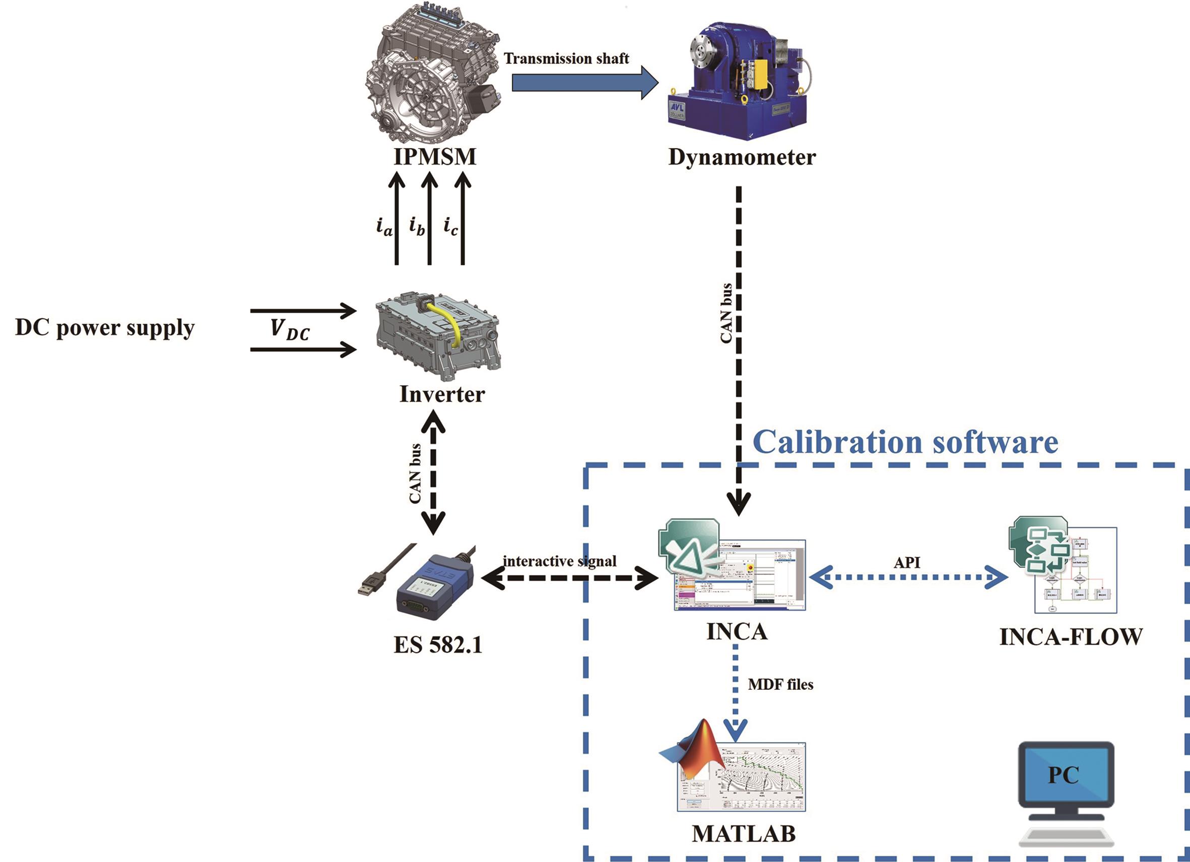
Figure 1. Schematic diagram of maximum torque per ampere (MTPA) calibration.
(1) Convenience of script writing: INCA FLOW already integrates a wide range of application programming interface (API) functions that can be used to call the calibration testing software INCA, which eliminates the need for users to write underlying software for interacting with INCA [23]. Engineers only need to configure the test files and experiment environment interface to call INCA, enabling them to achieve automatic testing through graphical programming in INCA FLOW.
(2) Efficient data process: The test data is processed in batch and visualized through MATLAB scripts, significantly enhancing the efficiency of data process.
2. Construction of the Development Environment
2.1. Experimental Test Bench
An experimental laboratory bench was created to evaluate the performance of the proposed calibration method. An IPMSM with a rated power of 75 kW was selected as the test object, its key parameters are given in Table 1. The controller communicates with the testing computer via the CAN bus, which includes a driver circuit board and an inverter, among other components. Its function is to run the control logic program and modulate the required three-phase currents to drive the motor. The dynamometer is connected to the motor through the drive shaft and provides real-time feedback of the measured output torque of the motor to the testing computer via the CAN bus. The test bench is shown in Figure 2.
Table 1. Key parameters of the interior permanent magnet synchronous motor (IPMSM).


Figure 2. Picture of experimental test bench: (a) controller, (b) interior permanent magnet synchronous motor (IPMSM), (c) transmission shaft, (d) dynamometer, (e) bench console.
2.2. Testing Software and MTPA Strategy
INCA and INCA FLOW software from ETAS GmbH is utilized to develop an automatic calibration program for IPMSM in this work. INCA sends calibration parameter signals via CAN to control the IPMSM. INCA FLOW utilizes a diverse set of API functions to invoke INCA, and creates intuitive models of calibration procedures using standard modeling blocks.
The electromagnetic torque expression for IPMSM is:

In the equation, Ld and Lq represent the components of stator inductance along the direct and quadrature axes respectively. id and iq correspond to the stator currents along the direct and quadrature axes respectively. Ψf represents the magnetic flux, and p0 denotes the number of pole pairs in the motor.
In the rotating d-q coordinate system, the relationship between the current angle θ, and the current vector is, is as follows:

The Equation (1) can be expressed as:

The first part on the right of Equation (4) corresponds to the field torque, and the last is the reluctance torque. The permanent magnets of the IPMSM are embedded in the rotor, and its q-axis inductance is larger than the d-axis inductance [24]. When θ < π/2, the reluctance torque is negative, indicating braking torque. When θ > π/2, the reluctance torque is positive, representing driving torque. To achieve the most efficient driving torque, it can be inferred that the motor's current vector should operate in the second quadrant (id < 0, iq > 0). Based on Equation (1), it can be observed that the magnitude of the motor torque depends on the two components of the stator current. Furthermore, for every torque value, there are countless combinations of id and iq that correspond to it. When the motor operates below base speed, the MTPA strategy is commonly employed for control. In this strategy, when a certain torque demand is specified, the aim is to minimize the stator current vector, thereby enhancing motor efficiency and power density.
The motor control software adopts a control method based on LUTs, as illustrated in Figure 3. When the motor operates below base speed, referring to the d-axis current LUT with the requested torque and motor speed, the desired value of the d-axis current id* is obtained. Similarly, using the requested torque and id* to consult the q-axis current LUT, the desired q-axis current iq* is determined. These target currents are then compared with the real-time currents that have undergone Clark and Park transformations. The difference is processed through PI control, inverse Park transformation, and Space Vector Pulse Width Modulation (SVPWM). Finally, the control is achieved by selectively turning on and off power switches in the inverter, which regulates the phase currents.
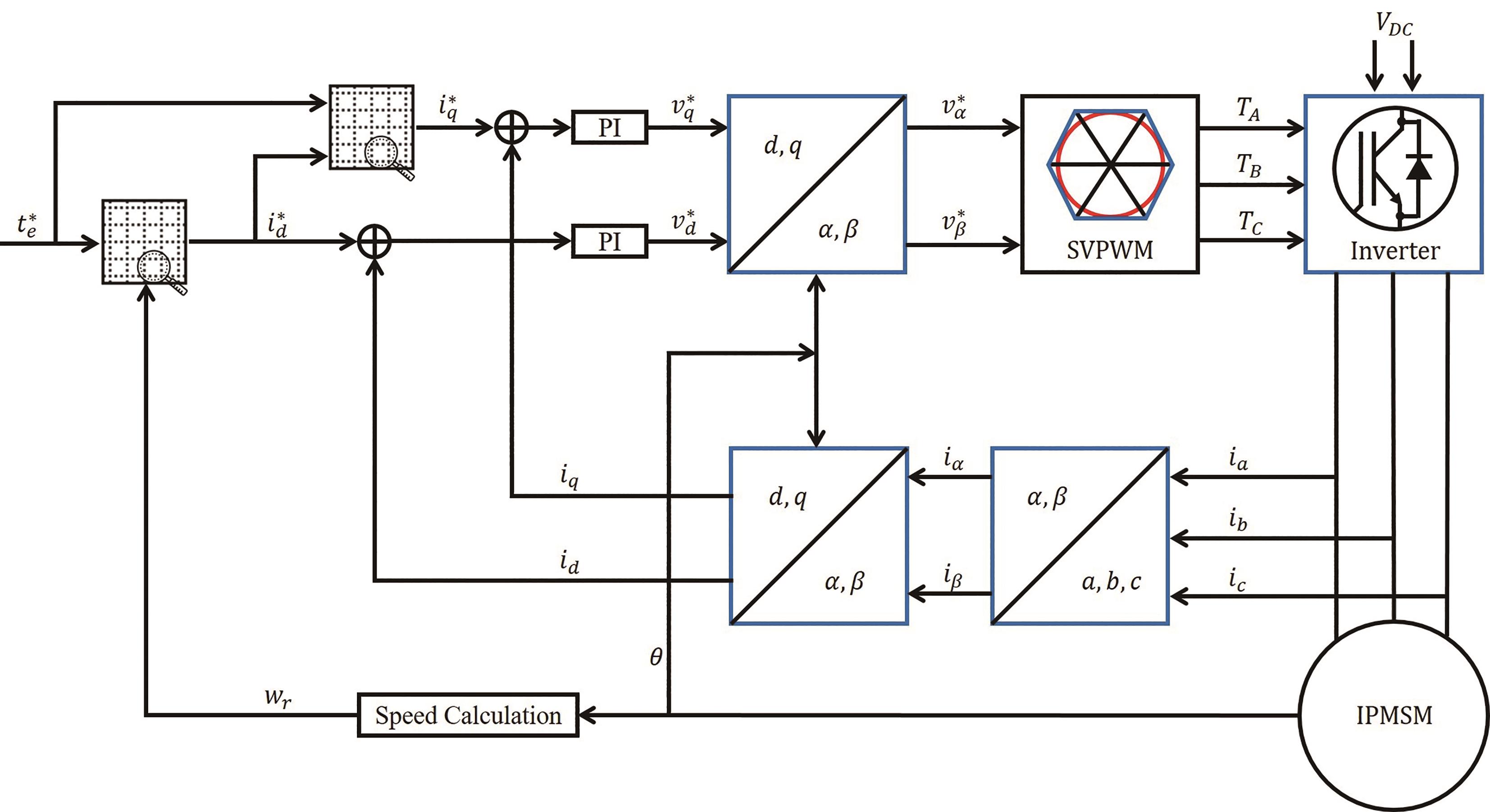
Figure 3. Interior permanent magnet synchronous motor (IPMSM) look-up table (LUT)-based controller block diagram.
3. Software Development of Automatic IPMSM Calibration
3.1. INCA FLOW-Based Automatic MTPA Testing
The MTPA testing process involves fixing the IPMSM at a base speed and setting the d-axis current and q-axis current to obtain the corresponding torque. By traversing all the required combinations of d- and q-axis currents, a torque table corresponding to each current combination can be obtained. To obtain more accurate MTPA data results, it is preferable to have a finer resolution for the current values. However, this increases the testing workload significantly. Therefore, an INCA FLOW-based MTPA automatic testing method is adopted. This method automates the testing process, addressing the issues of frequent parameter adjustments and potential errors caused by human operation. It greatly improves the testing efficiency by automating the testing procedure using INCA FLOW, thereby reducing the workload and enhancing the precision of the MTPA data results.
The automatic testing process is shown in Figure 4a. First, INCA is connected with USB CAN FD Bus Interface (ES 582.1) to establish communication with the motor. Then, the INCA testing environment parameters, including the target speed and target d-axis current, are set up by configuring the test file, and initializing them. The motor speed is set and traverses all d-axis currents at each speed. For each d-axis current, iterate through the q-axis currents up to the maximum allowable value, and save the data. Once all operating points have been executed, the testing is completed. Utilizing the graphical programming capabilities of INCA FLOW, the MTPA testing process is implemented, as shown in Figure 4b.
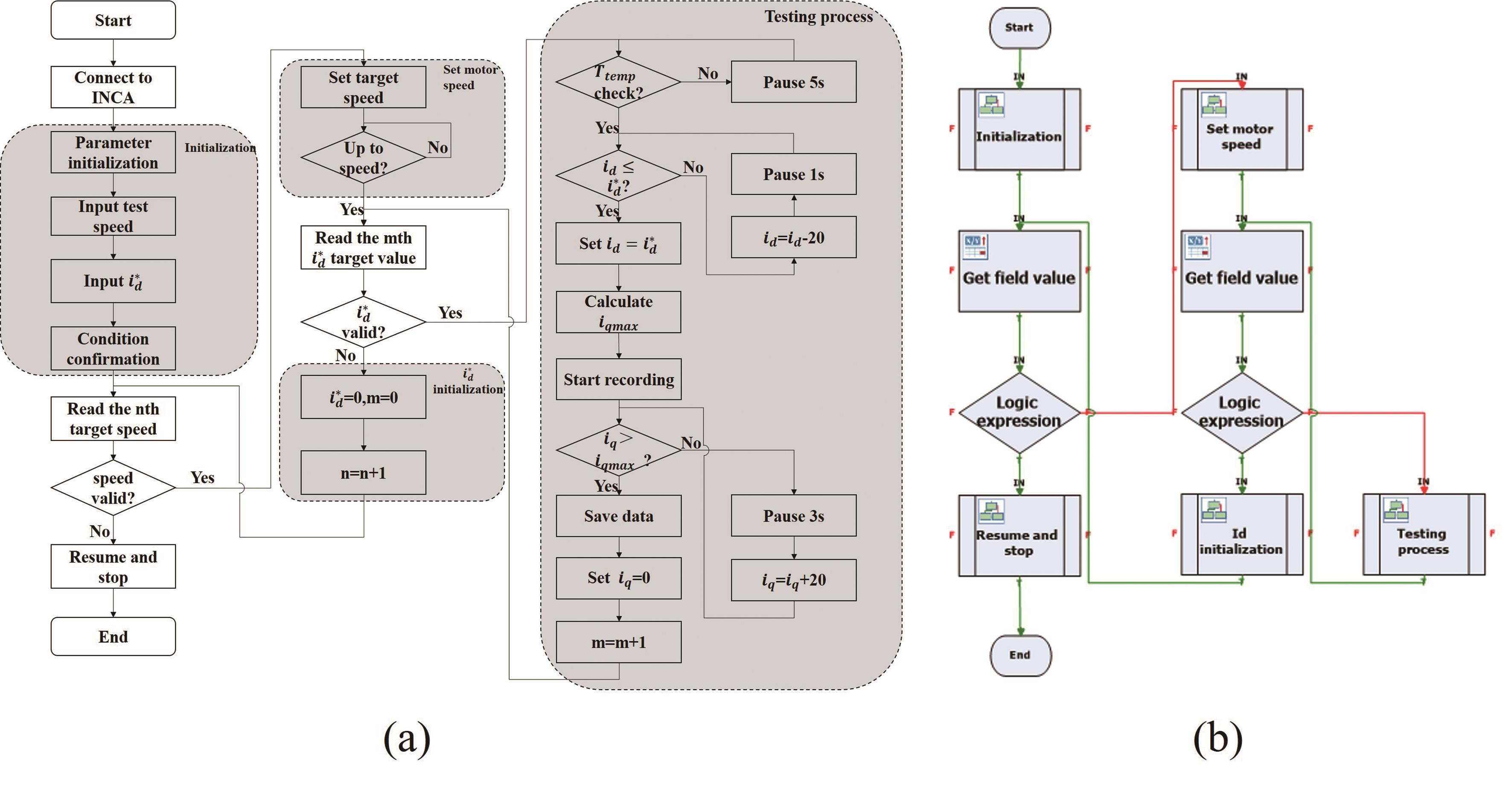
Figure 4. (a) Flow chart of MTPA test, (b) Graphical main program for MTPA test.
Compiling and running the aforementioned program initiates the loading of the testing program. INCA FLOW will first display a runtime window and then invoke the INCA software by calling API functions. When the automatic testing program is running, it will prompt for input of the testing conditions. After confirming the accuracy of the conditions, the program will proceed to determine the actual states of speed and temperature. Finally, it will enter the MTPA testing process (Figure 5).
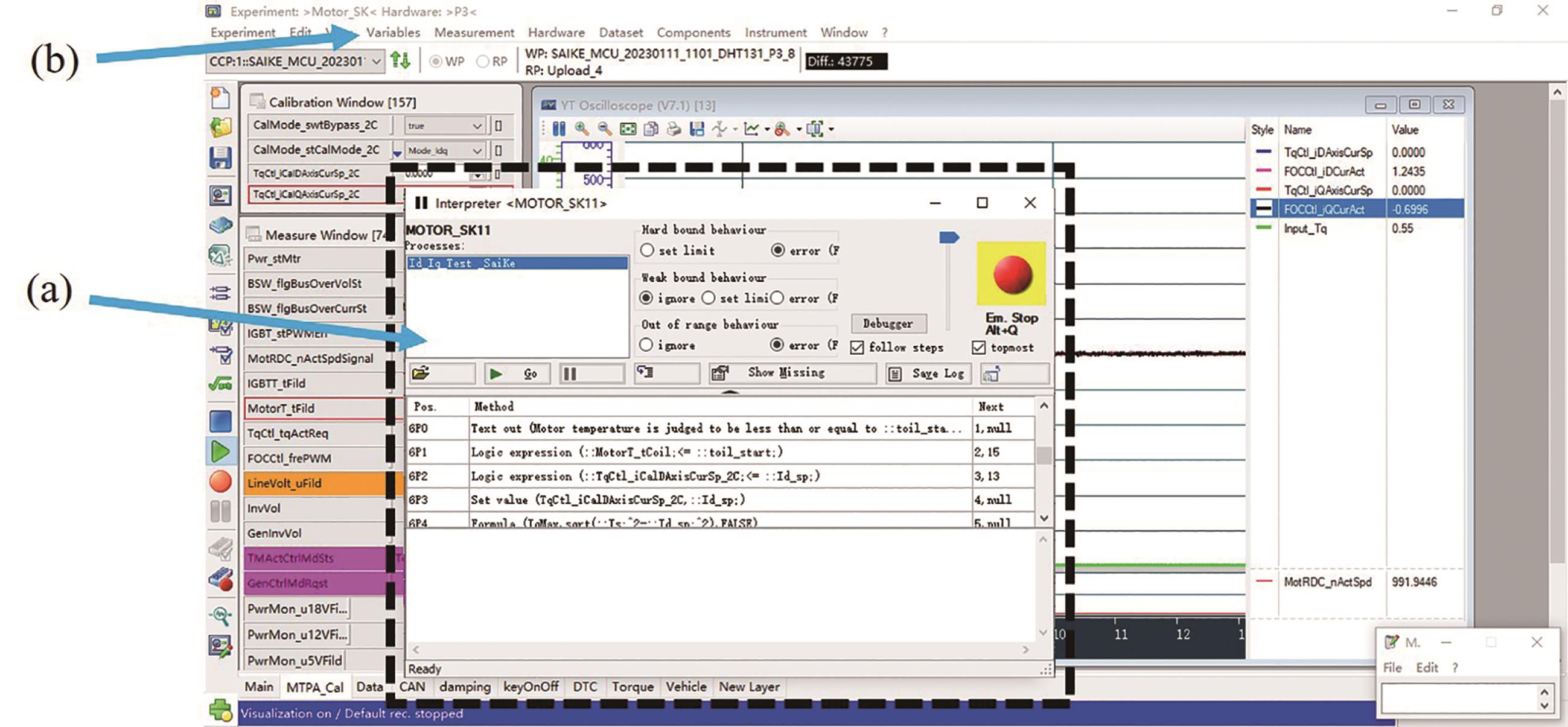
Figure 5. (a) INCA FLOW calls, (b) INCA for testing.
3.2. MATLAB-Based Data Processing
After the completion of automatic testing, a series of data files are generated, which include motor torque, and d- and q-axis currents. Extracting the torque corresponding to each combination of d- and q-axis currents to fit the MTPA curve. In this study, the MATLAB-based scripting language and Graphical User Interface (GUI) are developed to create an automatic processing software that efficiently and accurately handles the data and fits the MTPA curve. The MATLAB GUI provides a graphical interface for controlling the software application through user clicks. Users can interact with the program by selecting and activating controls using mouse or keyboard input.
3.2.1. Software Interface Design
The design of the software interface should adhere to the principles of simplicity, reliability, and interactivity [25,26]. Using MATLAB GUI for visual software development typically involves four steps:
(1) Identifying the main functions of the software and dividing them into several sub-functional modules.
(2) Designing user interfaces based on the sub-functional modules with a focus on simplicity and intuitiveness.
(3) Writing callback functions for menu bars, buttons, coordinate axes, and status bars on the user interface, and performing software functionality testing item by item.
(4) Compiling and publishing the software.
The data processing flow mainly involves extracting and analyzing data under different operating conditions, calculating the MTPA curves based on the processed data, displaying them through plots, and exporting the calculation results and images in document format. To ensure clear logical flow and readable code during the software design process, the software functionalities are divided into five main modules as shown in Figure 6a: File loading, Data extraction, Data processing, Curve plotting, and Data export.

Figure 6. (a) Overall software framework, (b) software interface.
3.2.2. Software Functionality Overview
The functional interface of developed software is shown in Figure 6b. The left area contains the parameter settings for data loading and extraction, while the right area includes parameter settings for data processing and curve plotting. After loading the file, extracting and processing data, and setting the data parameters, clicking "Run" will immediately initiate the curve plotting and generate the MTPA results in real-time. The functionality is described as follows:
(1) Graphical user interface module: This module facilitates the interaction between the software and the user, which includes a menu bar, functional interfaces, and a status bar. The menu bar contains file import and help functions, each with several submenus, providing convenient functionality for software usage. The software interface is shown in Figure 6b, with the data file information panel and list in the upper-left section. After successful data import, the information panel displays the file path and quantity, while the list shows the names of all loaded files for easy verification. The text boxes in the lower-left and upper-right sections are used for setting data extraction and data processing parameters, respectively. The buttons in the lower-left section are used for executing data processing and exporting results. The central area of the software includes a graph display window and a data processing result table for plotting data graphs and outputting calculation results.
(2) File loading module: This module is used to load file information and assess the validity of the files, excluding any invalid files. The data storage path is scanned to achieve the batch loading and import of valid data files.
(3) Data extraction module: This module parses the measurement data and enables batch reading of data files. Firstly, the module sorts the files based on the d-axis current in descending order. Since the measurement data collected by INCA save as the MDF (Measurement Data Format) file format, this study uses MATLAB scripts to parse and read the data [27]. The read data is interpolated and filtered, and the corresponding torque values are selected based on the q-axis current. After processing one MDF file, the module moves on to the next file, achieving batch processing of data files (Figure 7).

Figure 7. Batch processing of data files.
(4) Data processing module: This module is the core module of the software's functionality and is responsible for MTPA calculation. The main steps are as follows:
a) The module analyzes the extracted data and removes data points that do not meet the requirements (Figure 8).

Figure 8. Remove abnormal test point data.
b) Using the interpolation function provided by MATLAB, 2-D interpolation is performed on the d-axis current, torque, and q-axis current. The q-axis current values corresponding to different d-axis current values for the same torque level are obtained during this interpolation process (Figure 9).
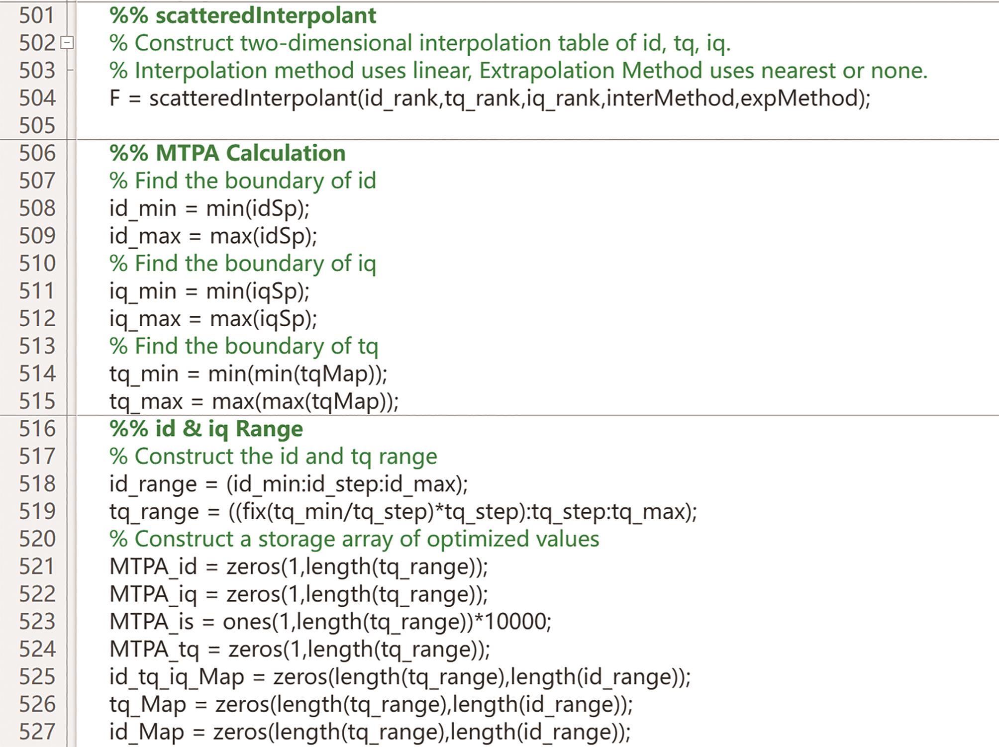
Figure 9. Build data relationships.
c) Based on Equations (2) and (3), the module calculates the current vector, is, where the smallest d- and q-axis currents of is represent the MTPA point for that torque.
d) The MTPA points are calculated incrementally by increasing the torque value until reaching the maximum torque point. The MTPA curve is drawn from the processed data (Figure 10).
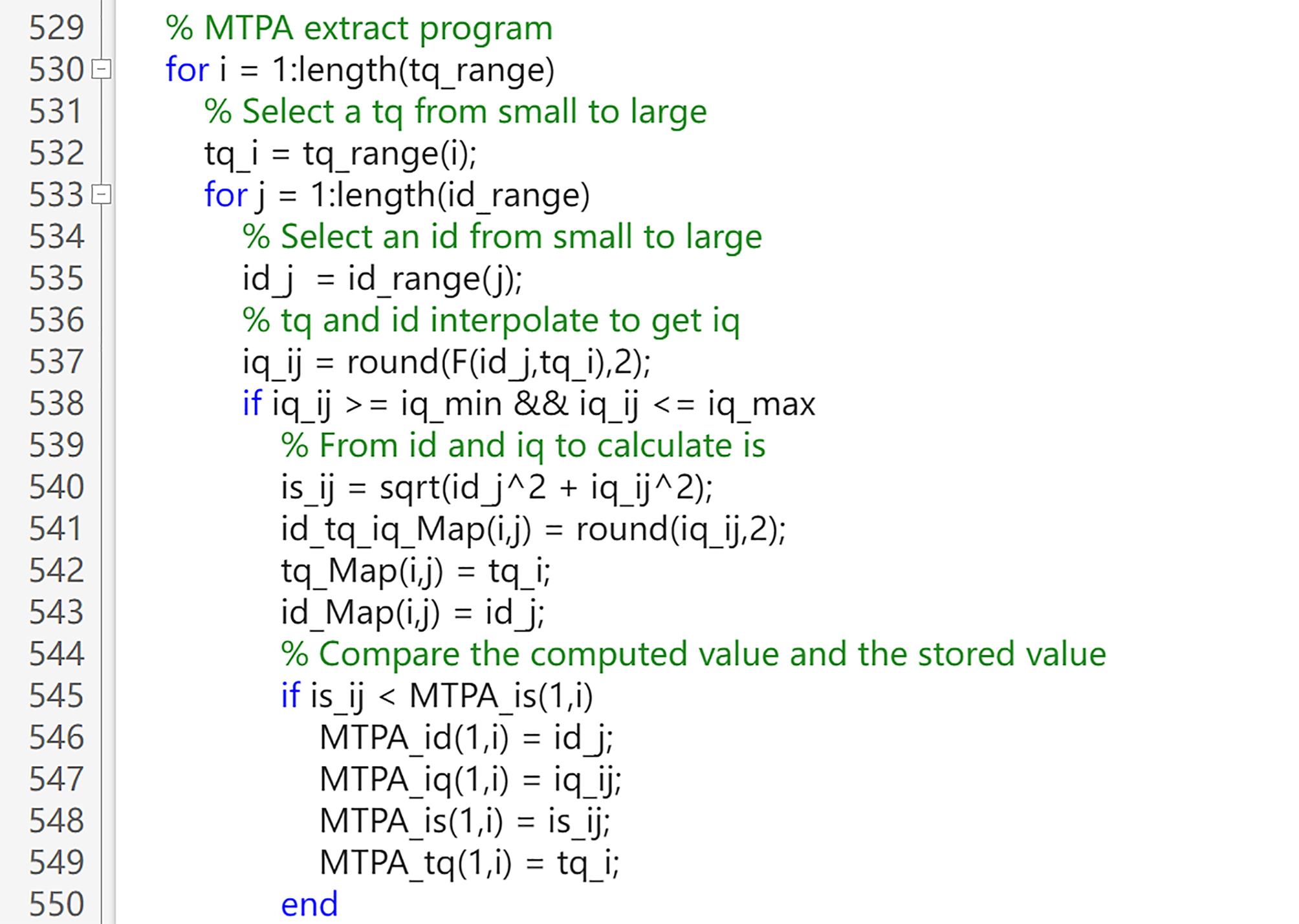
Figure 10. Calculate MTPA points.
(5) Curve plotting module: This module plots the original data processed by the data extraction module and the MTPA curve generated by the data processing module on the same graph, achieving data visualization. This module facilitates the identification of deviations and errors in the data, making it easier for test personnel to optimize the data (Figure 11).
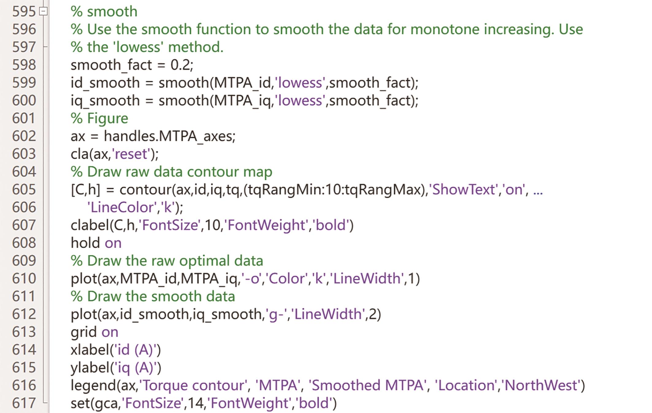
Figure 11. Draw MTPA curve.
(6) Data export module: This module exports the data results as Excel document, including the MTPA curve and MTPA data.
4. Test Results and Discussion
During the experiments, the IPMSM operates in the current closed-loop mode while the load speed is provided by a dynamometer. INCA FLOW invokes INCA to control d- and q-axis currents and stores the test data for each d-axis current with a range of q-axis currents as a file. INCA FLOW achieves the ability of the motor's current and speed control, motor signals monitor, and automatic MTPA testing.
After the motor bench testing is completed, the MTPA curve is obtained by executing the data processing program written in MATLAB. Operating at 1000 rpm, for example, these torque contours consist of 772 test points (Figure 12a). According to these test points, the MTPA points (mark circle) are calculated by running data process modules c) and d). The MTPA curve can be drawn by simulating these MTPA points. To eliminate the extreme values and measurement errors, the MTPA curve is subjected to a smoothing process, resulting in a smoothed curve (green line). However, the MTPA curve is not a perfectly smooth curve (red frame), which is mainly due to deviations in the motor current control loop. As shown in Figure 12b, the discrepancy corresponding to the abnormal points on the MTPA curve can be observed as caused by the actual currents not following the desired currents (with an actual-target current difference of approximately 10 A). These abnormal data points lead to inaccurate calibration of the d- and q-axis currents LUTs, resulting in significant deviations in the torque achieved through the LUTs. Thus, the corresponding control parameters of the software should be optimized and calibrated to reduce the torque control error of the motor.
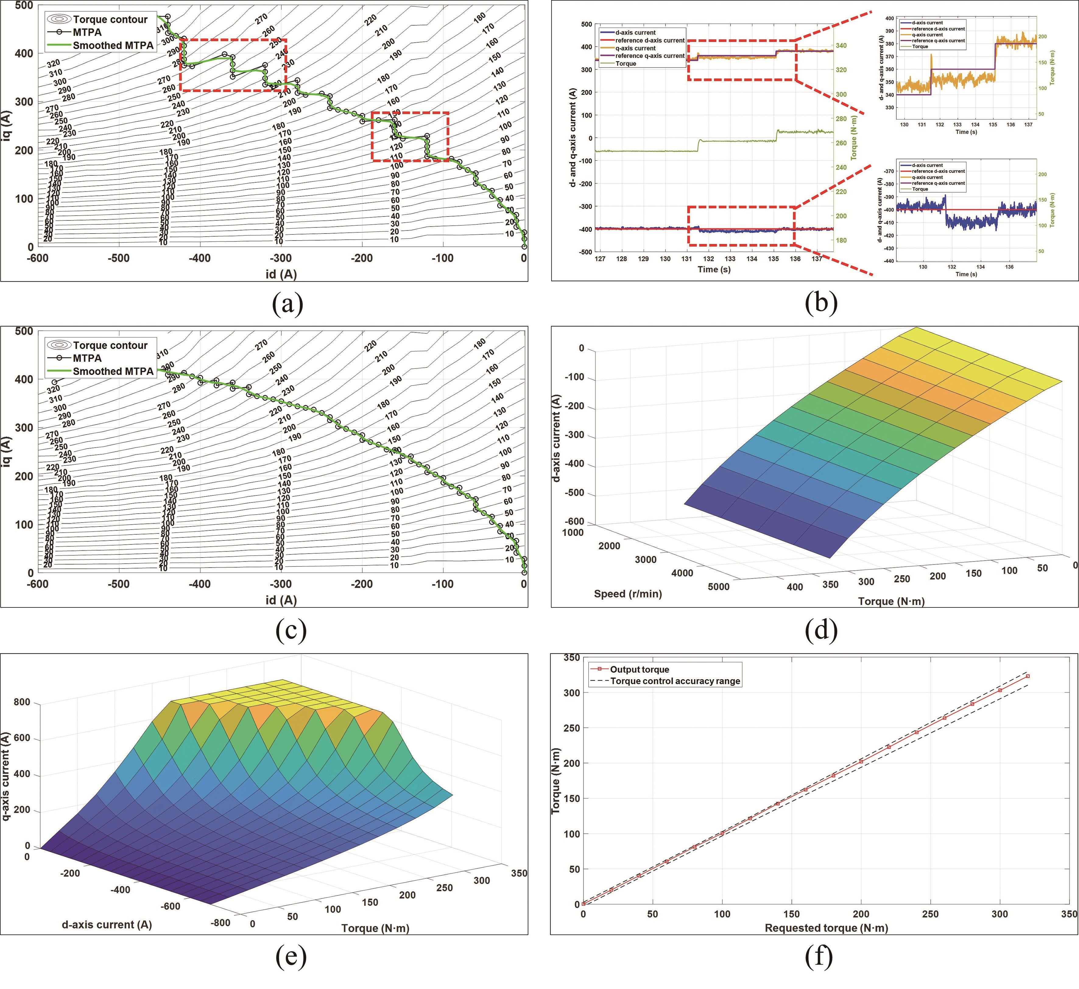
Figure 12. Results of MTPA: (a) process data to generate MTPA curve, (b) one of the outlier data (id*=-400 A, iq*=360 A), (c) MTPA curve after optimizing, (d) d-axis current LUT, (e) q-axis current LUT, (f) torque control accuracy of the MTPA.
With continuous optimization and calibration, the optimal motor parameters are determined to retest the abnormal points. Replace the abnormal data with the retest data, the MTPA curve after optimizing can be obtained by running data process modules (Figure 12c), which meets the requirements of the software. Based on the MTPA data, the d-axis and q-axis current LUTs for the control software can be generated using linear interpolation (Figure 12d,e). The d-axis current LUT below the base speed is obtained by interpolating the MTPA’s d-axis currents. The q-axis current LUT is generated by interpolating the entire set of test data, which is used to not only seek the q-axis currents for the MTPA but also query the q-axis currents during weak magnetic conditions. When the motor operates below the base speed, the controller queries these two tables to obtain id* and iq* respectively for controlling the motor torque.
To validate the accuracy of the MTPA data, the IPMSM is operated in the torque closed-loop mode with a controlled speed of 1000 rpm. The desired torque of the IPMSM is controlled, and the output torque is observed. The accuracy of the torque control in the MTPA data is determined by analyzing the difference between the desired torque and the output torque (Figure 12f). The torque accuracy is ±3 N·m when the motor torque is within 100 N·m. For torque values exceeding 100 N·m, the torque accuracy is ±3%. These results satisfy the required torque control accuracy of the motor. With the implementation of this method, the time required for MTPA calibration has been reduced from 210 min to 50 min, resulting in a remarkable efficiency improvement of 320%.
5. Conclusions
This study adopts a combined approach using INCA FLOW and MATLAB to perform MTPA parameter calibration of the IPMSM. The automatic testing scripts in INCA FLOW enhance testing efficiency and reduce losses caused by human errors. The data processing scripts written in MATLAB not only enable fast processing of test data but also facilitate visual representation of MTPA results. These advantages enable the testing engineers to quickly and intuitively analyze MTPA results, significantly improving calibration efficiency. Benefiting from the convenience of graphical programming in INCA FLOW and the efficiency of data processing in MATLAB, this method not only supports the MTPA calibration of IPMSMs but also can be applied to other testing tasks, such as calibrating automotive powertrain systems of engines, transmissions, and motors.
Author Contributions: Conceptualization, methodology, software, validation, writing—original draft, visualization, Z.L., R.H.; data curation, formal analysis, writing—review and editing, R.H., X.Z.; supervision, project administration, K.C., G.L. All authors have read and agreed to the published version of the manuscript.
Funding: This research received no external funding.
Data Availability Statement: Statement: Not applicable.
Acknowledgments: The authors thank the technologists at Liuzhou Saike Technology Development Co., Ltd., and other OEM partners for their collaborative effort and technical support.
Conflicts of Interest: The authors declare no conflict of interest.
References
- Zhou, X.; Jiang, J.; Hu, Z.; et al. Lightweight Materials in Electric Vehicles. International Journal of Automotive Manufacturing and Materials 2022, 1, 3. DOI: https://doi.org/10.53941/ijamm0101003
- Cai, W.; Wu, X.; Zhou, M.; et al. Review and development of electric motor systems and electric powertrains for new energy vehicles. Automotive Innovation 2021, 4, 3–22. DOI: https://doi.org/10.1007/s42154-021-00139-z
- Feng, S.; Magee, C.L. Technological development of key domains in electric vehicles: Improvement rates, technology trajectories and key assignees. Applied Energy 2020, 260, 114264. DOI: https://doi.org/10.1016/j.apenergy.2019.114264
- Geng, H.; Zhang, X.; Yan, S.; et al. Magnetic Field Analysis of an Inner-Mounted Permanent Magnet Synchronous Motor for New Energy Vehicles. Energies 2022, 15(11), 4074. DOI: https://doi.org/10.3390/en15114074
- Wang, H.; Li, C.; Zhang, G.; et al. Maximum torque per ampere (MTPA) control of IPMSM systems based on controller parameters self-modification. IEEE Transactions on Vehicular Technology 2020, 69(3), 2613–2620. DOI: https://doi.org/10.1109/TVT.2020.2968133
- Hassan, M.; Ge, X.; Woldegiorgis, A.T.; et al. A look-up table-based model predictive torque control of IPMSM drives with duty cycle optimization. ISA Transactions 2023, 138, 670–686. DOI: https://doi.org/10.1016/j.isatra.2023.02.007
- Zhang, Y.; Qi, R. High-efficiency flux weakening drive for IPMSM based on model predictive control. IEEE Transactions on Transportation Electrification 2022, 8(3), 3503–3511. DOI: https://doi.org/10.1109/TTE.2022.3160454
- Qi, X.; Zheng, C.; Zhang, Q. An Electric Vehicle Induction Motor Parameters Calibration Method Based on Deep Deterministic Policy Gradient. Transactions of China Electrotechnical Society 2020, (20), 4266–4277. (In Chinese)
- Li, K.; Wang, Y. Maximum torque per ampere (MTPA) control for IPMSM drives based on a variable-equivalent-parameter MTPA control law. IEEE Transactions on Power Electronics 2018, 34(7), 7092–7102. DOI: https://doi.org/10.1109/TPEL.2018.2877740
- Dianov, A.; Tinazzi, F.; Calligaro, S.; et al. Review and classification of MTPA control algorithms for synchronous motors. IEEE Transactions on Power Electronics 2021, 37(4), 3990–4007. DOI: https://doi.org/10.1109/TPEL.2021.3123062
- Attaianese, C.; Di Monaco, M.; Spina, I.; et al. A variational approach to MTPA control of induction motor for EVs range optimization. IEEE Transactions on Vehicular Technology 2020, 69(7), 7014–7025. DOI: https://doi.org/10.1109/TVT.2020.2983908
- Alzayed, M.; Chaoui, H.; Farajpour, Y. Dynamic direct voltage MTPA current sensorless drives for interior PMSM-based electric vehicles. IEEE Transactions on Vehicular Technology 2022, 72(3), 3175–3185. DOI: https://doi.org/10.1109/TVT.2022.3219763
- Chowdhury, M.M.; Haque, M.E.; Saha, S.; et al. An enhanced control scheme for an IPM synchronous generator based wind turbine with MTPA trajectory and maximum power extraction. IEEE Transactions on Energy Conversion 2017, 33(2), 556–566. DOI: https://doi.org/10.1109/TEC.2017.2769126
- Zhang, Z.; Shen, A.; Li, P.; et al. MTPA-based high-frequency square wave voltage signal injection strategy for IPMSM control. Journal of Power Electronics 2021, 21, 1461–1472. DOI: https://doi.org/10.1007/s43236-021-00284-y
- Li, K.; Wang, Y. Maximum torque per ampere (MTPA) control for IPMSM drives using signal injection and an MTPA control law. IEEE Transactions on Industrial Informatics 2019, 15(10), 5588–5598. DOI: https://doi.org/10.1109/TII.2019.2905929
- Windisch, T.; Hofmann, W. Automatic MTPA tracking using online Simplex algorithm for IPMSM drives in vehicle applications. In 2014 IEEE Vehicle Power and Propulsion Conference (VPPC). IEEE: Piscataway, NJ, USA, 2014; pp. 1–6. DOI: https://doi.org/10.1109/VPPC.2014.7007024
- Wang, G.; Li, Z.; Zhang, G.; et al. Quadrature PLL-based high-order sliding-mode observer for IPMSM sensorless control with online MTPA control strategy. IEEE Transactions on Energy Conversion 2012, 28(1), 214–224. DOI: https://doi.org/10.1109/TEC.2012.2228484
- Antonello, R.; Carraro, M.; Zigliotto, M. Maximum-torque-per-ampere operation of anisotropic synchronous permanent-magnet motors based on extremum seeking control. IEEE Transactions on Industrial Electronics 2013, 61(9), 5086–5093. DOI: https://doi.org/10.1109/TIE.2013.2278518
- Nguyen, Q. K.; Petrich, M.; Roth-Stielow, J. Implementation of the MTPA and MTPV control with online parameter identification for a high speed IPMSM used as traction drive. In 2014 International Power Electronics Conference (IPEC-Hiroshima 2014-ECCE ASIA). IEEE: Piscataway, NJ, USA, 2014; pp. 318–323. DOI: https://doi.org/10.1109/IPEC.2014.6869600
- Jung, S.Y.; Hong, J.; Nam, K. Current minimizing torque control of the IPMSM using Ferrari’s method. IEEE Transactions on Power Electronics 2013, 28(12), 5603–5617. DOI: https://doi.org/10.1109/TPEL.2013.2245920
- Yang, N.; Luo, G.; Liu, W.; et al. Interior permanent magnet synchronous motor control for electric vehicle using look-up table. In Proceedings of the 7th international power electronics and motion control conference. IEEE: Piscataway, NJ, USA, 2012; Volume 2, pp. 1015–1019. DOI: https://doi.org/10.1109/IPEMC.2012.6258940
- Cheng, B.; Tesch, T.R. Torque feedforward control technique for permanent-magnet synchronous motors. IEEE Transactions on Industrial Electronics 2010, 57(3), 969–974. DOI: https://doi.org/10.1109/TIE.2009.2038951
- Cho, Y.; Huber, T.; Lauff, U.; et al. Optimisation of gasoline engines automation and machine learning techniques in calibration. ATZelektronik Worldwide 2017, 12(3), 48–53. DOI: https://doi.org/10.1007/s38314-017-0031-4
- Xia, J.; Xu, J.; Huang, Y.; et al. Parameter-Estimation-Based Adaptive MTPA Control for Interior Permanent Magnet Synchronous Motors. In 2019 6th International Conference on Control, Decision and Information Technologies (CoDIT). IEEE: Piscataway, NJ, USA, 2019; pp. 397–402. DOI: https://doi.org/10.1109/CoDIT.2019.8820640
- Faghih, B.; Azadehfar, D.M.R.; Katebi, P. User interface design for e-learning software. arXiv preprint 2014, arXiv:1401.6365.
- He, S.; Li, P. A MATLAB based graphical user interface (GUI) for quickly producing widely used hydrogeochemical diagrams. Geochemistry 2020, 80(4), 125550. DOI: https://doi.org/10.1016/j.chemer.2019.125550
- Stuart McGarrity. MDF Import Tool and Function Available online: https://www.mathworks.com/matlabcentral/fileexchange/9622-mdf-import-tool-and-function (Accessed on 23 June 2023).


