Downloads
Download


This work is licensed under a Creative Commons Attribution 4.0 International License.
Article
Complete Workflow of Internal Nozzle Flow and Engine Simulation Using Multi-Component Fuel at Flash Boiling Conditions
Bejoy Mandumpala Devassy 1, Yidan Zhang 2, * , Enyuan Zhang 2, and Long Zhou 2
1 AVL LIST GmbH, Hans-List-Platz 1, Graz 8020, Austria
2 AVL List Technical Center (Shanghai) Co., LTD. Shanghai 201206, China
* Correspondence: yidan.zhang@avl.com
Received: 17 May 2023
Accepted: 1 September 2023
Published: 14 September 2023
Abstract: At present 3D CFD simulation tools are getting more and more importance for addressing complex physical problems. This article presents a complete virtual analysis of the in-cylinder workflow in gasoline engine at flash boiling condition. Using the standard gasoline surrogate fuel PACE-20, properties of different fuel components was considered both the nozzle and in-cylinder flow. The flow, evaporation, spray jet interaction and spray collapse under flash boiling condition was studied. Molar density fraction was used to describe fuel component distribution for both gas phase and liquid phase. Based on nozzle flow simulation result, in-cylinder simulation has been done, the distribution of different fuel components and the influence on wall film, flame propagation, emission distribution has been studied. It shows that the simulation results have good agreement with testing data, and it proves the model validation for gasoline engine virtual development method under flash boiling conditions.
Keywords:
flash boiling spray internal nozzle flow in-cylinder workflow combined simulation validation1. Introduction
As global environmental issues are becoming even more critical, there is further increasing pressure on the automotive industry to develop engines with reduced emissions and better fuel economy while meeting performance requirements.
At present, the mainstream fuel injection technology for gasoline engine is gasoline direct injection (GDI), which means that gasoline is directly injected into cylinder during intake stroke or compression stroke. Proper mixture for ignition will then be generated by liquid fuel droplets breakup, evaporation and mixing with air. Due to high injection pressure together with heat transfer from cylinder head and in-cylinder gas, the temperature of GDI injector is usually high, this may cause fuel pressure drop rapidly to the saturated vapor pressure soon after it’s injected into cylinder and cause rapid boiling and atomization of high temperature fuel, which form flash boiling spray [1].
Under flash boiling condition, the liquid fuel will breakup much faster, and the spray usually have smaller liquid penetration and bigger cone angle, this will heavily influence the combustion in cylinder, and influence the emission level for CO2, NOx and Soot. It’s necessary to understand the physics happening in GDI injector nozzles for multi-component fuels and its effect on engine emission is a key factor to achieve the emission goals.
There are many flash boiling related research all over the world, and the potential of flash boiling spray to improve gasoline engine performance has been proved by different analysis, including research by Zhao [2], Drake [3], Xu [4] and Zhang [5]. More detail research has been taken on in recent years, Aleiferis [6] studied the influence of flash boiling spray on mixture generation and flame propagation, Li [7] studied the sensitivity of flash boiling spray to injection back pressure.
Virtual method is more and more popular due to short turnaround time and low price. 3D computational fluid dynamics (CFD) simulation could help to get whole picture of in-cylinder conditions such as pressure, temperature, fuel concentration and combustion process from 3D view. With the continuous enhancement of computing resources, the application of simulation method has also become unprecedentedly popular, almost all original equipment manufacturers (OEMs) are using simulation method to develop combustion system. In this study, AVL FIRETM M was used to do the study, and the validation with experiment has been done.
The unique solution offered by AVL FIRETM M in this perspective is the complete workflow of internal nozzle flow and engine simulation. The key steps for a successful simulation: computer-aided design (CAD) preparation, mesh generation, setting up the simulation, calculation, post processing and report generation, all can be performed using this tool. Additionally, the strong property database for multi-component simulations is an advantage in AVL FIRETM M. Besides, a robust solver, advanced interfacial exchange models (mass, momentum, turbulence and energy) in multiphase, multi-component spray and combustion models etc. offer accurate and fast solution.
Based on study of this paper, engineers can understand every stage of fluid flow within the engine system, and to improve combustion efficiency and reduce pollutant.
Figure 1 shows the prediction of nozzle tip wetting simulations using single component iso-Octane as fuel at flash boiling conditions.
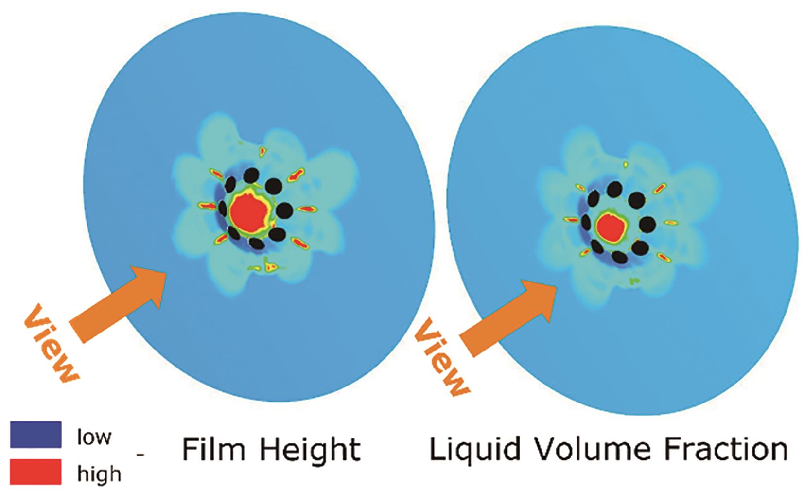
Figure 1. Nozzle tip wetting for single component (iso-Octane) at flash boiling conditions using AVL FIRE™ M simulations.
2. Multi-Component Fuel Injection Strategy in Gasoline Direct Injection Engines
The current strategy in Gasoline Direct Injection (GDI) Engines is to inject multi-component fuels (or surrogate fuels) at elevated temperature. This can initiate flash boiling which can lead to faster breakup, reduced penetration, and increased spray-cone angle. Thus, it impacts engine efficiency in terms of combustion quality, CO2, NOx and soot emission levels. Figure 2 shows the schematic of a flashing spray and the effect of flash boiling phenomenon in spray atomization.
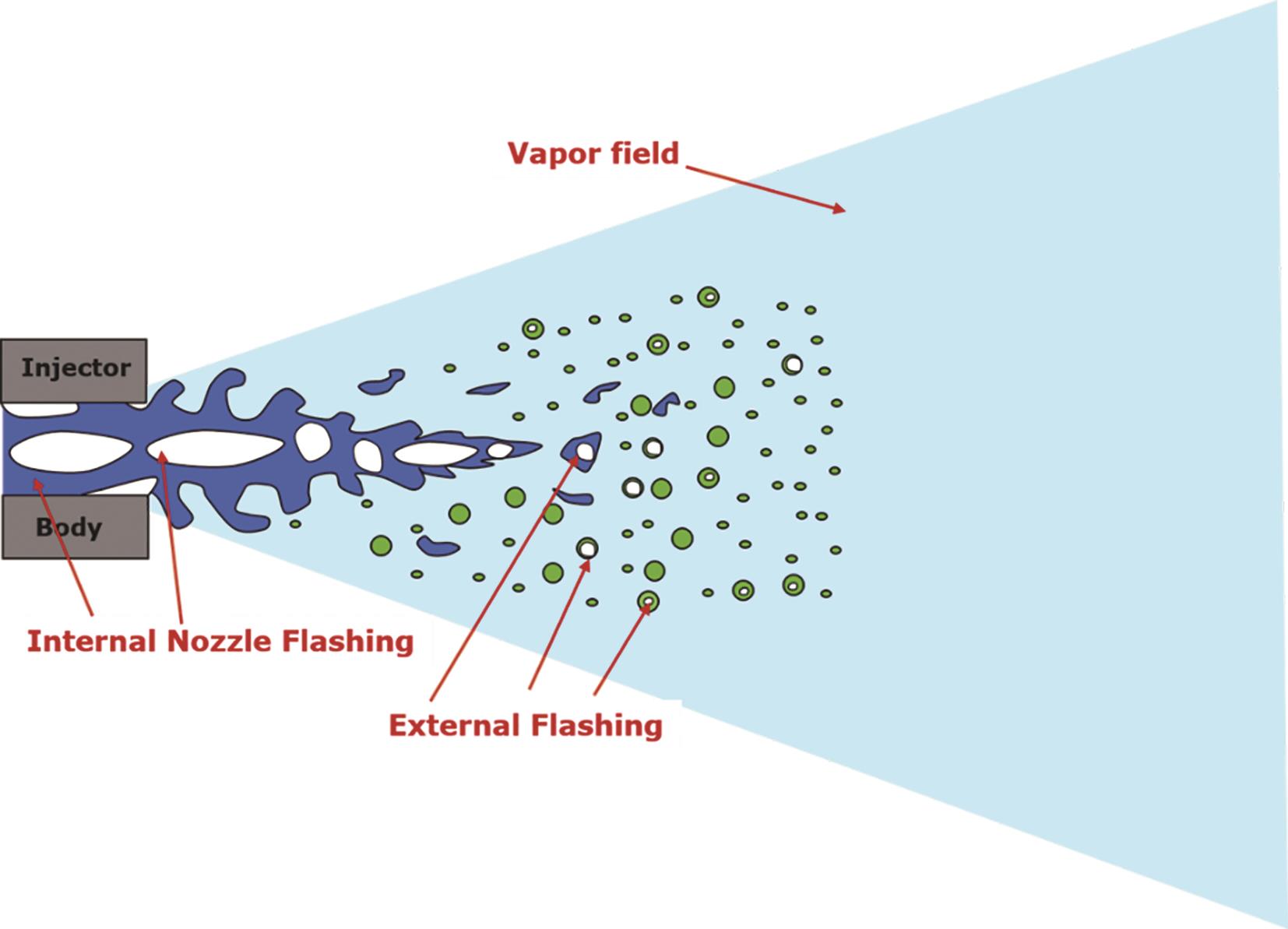
Figure 2. Schematic of a flash boiling spray. Showing the effect of internal and external flashing on spray atomization.
3. Workflow of Injector-Engine Simulation Model Used in This Study
Flash boiling is a phenomenon occurring when the preheated liquid is depressurized to the value below the liquid saturation pressure, or in terms of temperature—a phenomenon occurring when the liquid temperature exceeds its saturation temperature.
From the understanding of flashing simulation in engines, it is evident that the physics happening during the fuel injection process, injector geometry, etc. plays a key role and can affect the combustion and the quantity of final pollutants emitted. AVL FIRETM M is a unique tool which can perform these combined simulations in a much easier fashion. Figure 3 shows the two-step process to achieve this goal. In the first step, nozzle flow simulations are performed in a multiphase Eulerian framework and all flow variables are written in a nozzle interface for each nozzle holes as shown in Figure 3. These nozzle interface files are then used as boundary conditions, in the second step, for engine Lagrangian spray simulation.
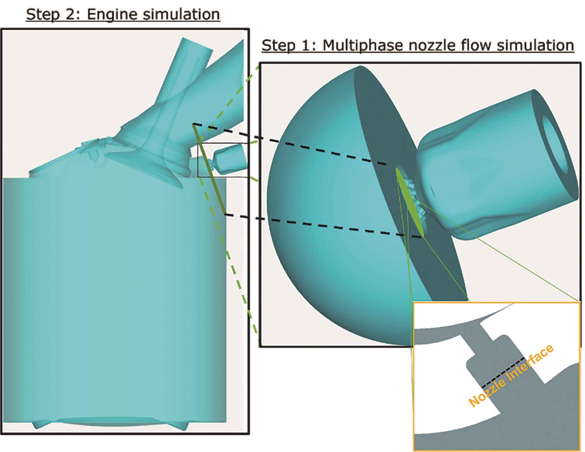
Figure 3. AVL FIRE™ M combined workflow of internal nozzle flow and engine simulation with a nozzle interface.
The flashing mass transfer rate is modeled by the advanced Hertz-Knudsen model considering the deviation from the thermodynamic-equilibrium conditions [8].
In the multiphase multi-component nozzle flow simulation, multiphase module was used to consider mass, momentum and energy exchange between gas phase and liquid phase, multi-component flash boiling model was used to consider mass exchange under flash boiling condition [9].
The correct definition of the properties of the components (or species) in the liquid and vapor mixtures is essential. AVL FIRETM M provides a "smart" Property Database (PDB) to the users containing a long list of materials which can be easily combined to make surrogate fuels as shown in Figure 4.
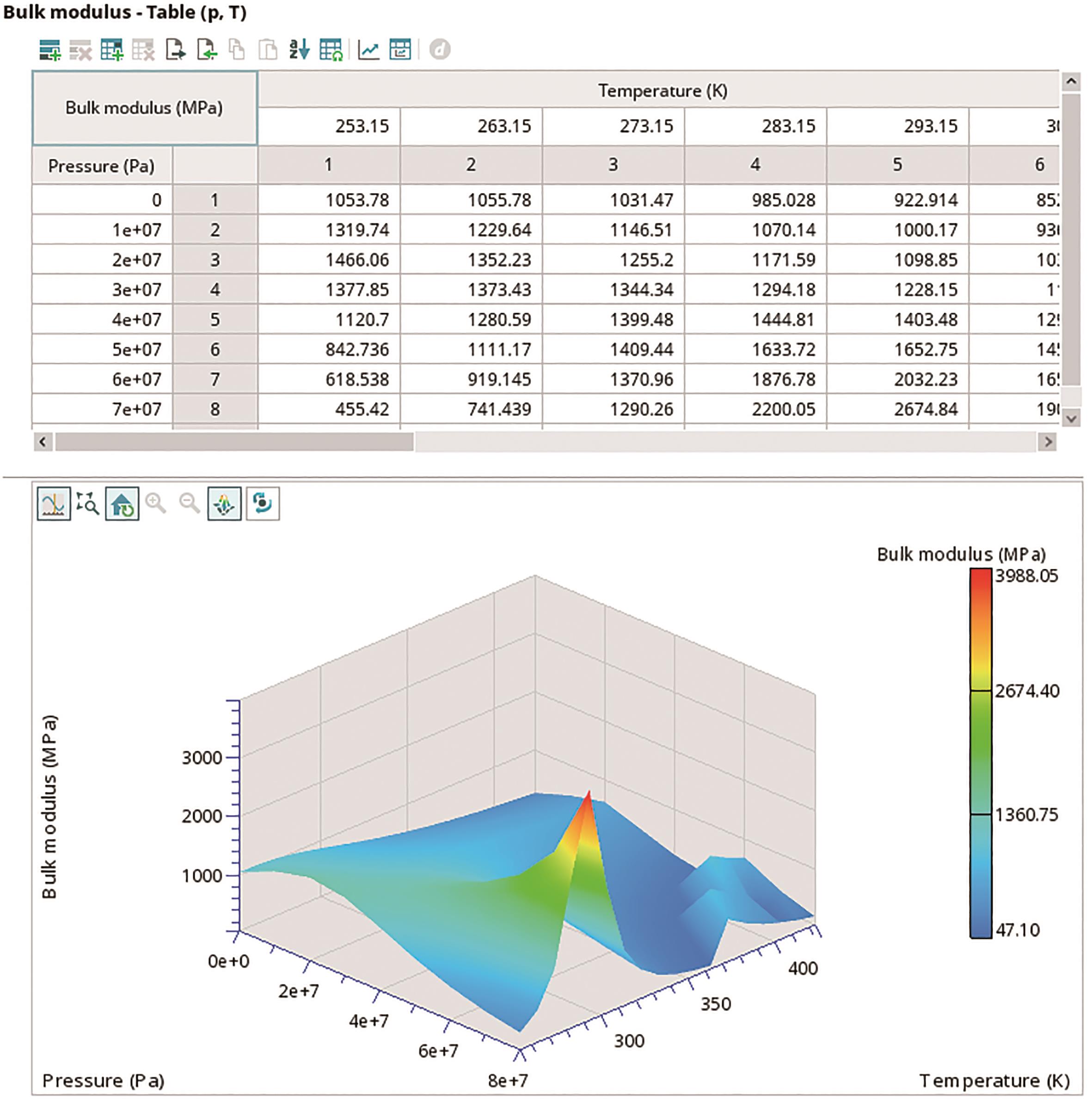
Figure 4. Bulk modulus of Ethanol fuel data from AVL FIRE™ M Property Database (PDB).
The details of system of equations and modeling of flash boiling is available in AVL FIRE™ M [10].
The nozzle file from nozzle flow simulation contains the details of all flow variables and is written in specific time intervals. Figure 5 shows the header part of one nozzle file containing all the information followed by flow variables of each element in the chosen selection. For multi-component simulation, the nozzle file also has the information of list of components (or species) of liquid and vapor composition involved in the simulation and the important variable, mass fraction, is then written to the nozzle files along with other flow variables.
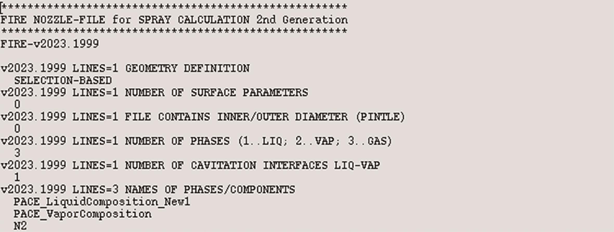
Figure 5. The header of a multi-component nozzle interface file.
4. "State of the Art" Multi-Component Fuel
The PACE-20* fuel is a gasoline surrogate which can reproduce the engine soot PM and PN trends of RD5-87 effectively, making it suitable for future experiments and modeling efforts. Partnership for Advanced Combustion Engines (PACE) is a DOE-funded consortium of 6 National Labs working towards a common goal. This "state of the art" multi-component fuel is used for the present investigation. 1,2,4-trimethylbenzene is a key component of PACE-20 (13.9%) and is likely the main contributor to soot formation. Figure 6 presents the list of components (mass fraction) in PACE-20 fuel.
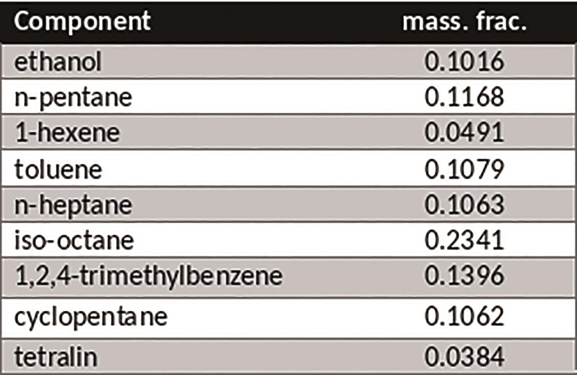
Figure 6. PACE-20 fuel components.
5. Simulation Results: The Prediction of Physics and Spray Behavior
Flash Boiling in fuel injector nozzle is a complex phenomenon. During this process the spray coming out from the injector is transient and turbulent. The asymmetry in the nozzle geometry also affects the jet behavior. When the needle starts moving, the onset of flashing vapor bubbles at the entrance edge of the nozzle or near the wall regions are observed where the flow direction is changed drastically.
Figure 7 presents the key flow variables during the injection process. The flow becomes aggressive over time due to sudden depressurization creating huge vapor cloud. Several physical phenomena; plume-plume interaction, spray collapse, hole-hole interaction. etc. are observed. This is visible in vapor volume fraction and velocity shown in Figure 7.
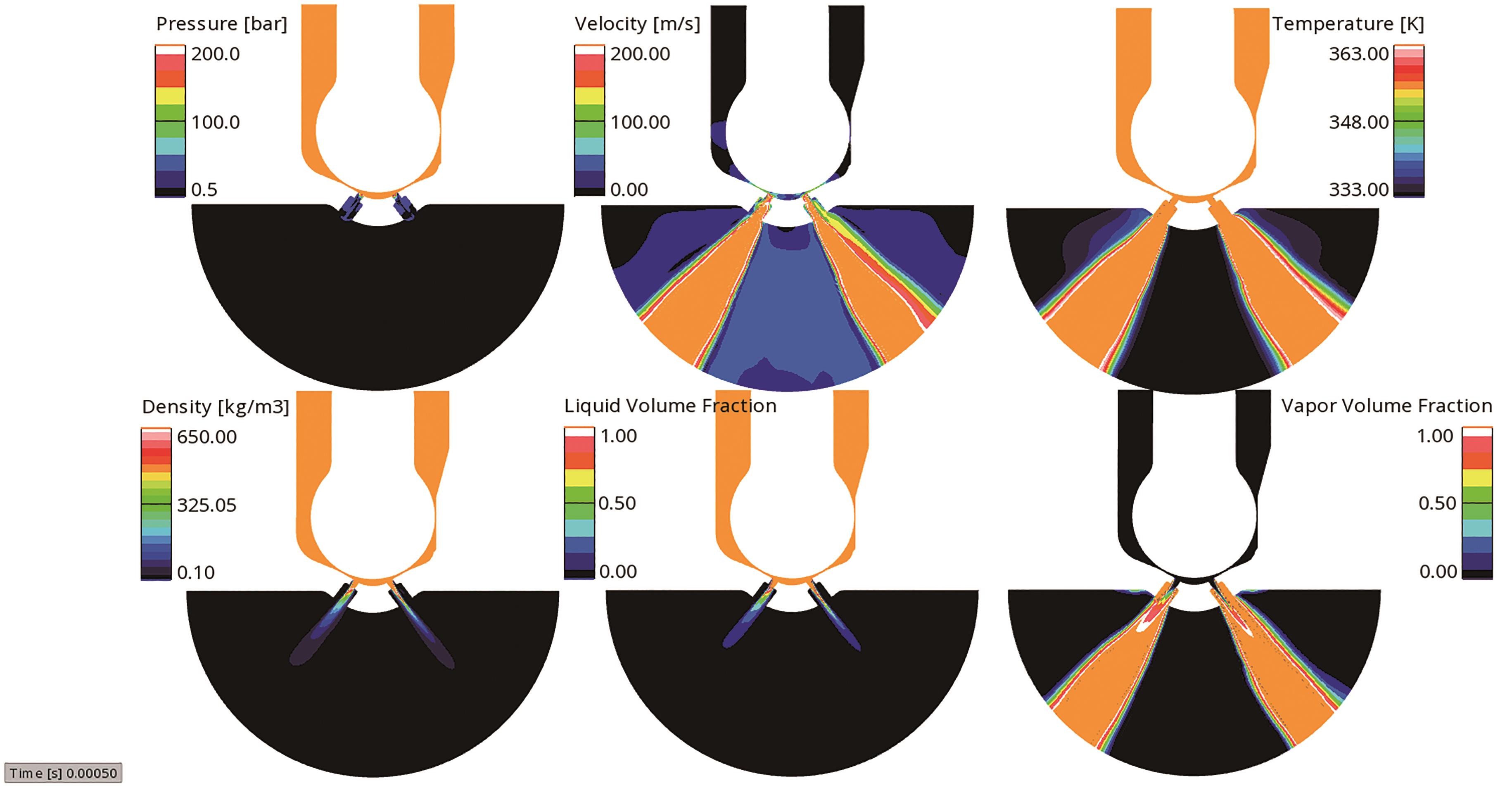
Figure 7. Key flow variables of a multiphase-multi-component nozzle flow simulation at 0.5 seconds after Start of Injection (SOI).
To understand the spray behavior of a multi-component jet, it is important to monitor closely how individual components in a liquid and vapor mixture behaves during the flashing process. Molar Density Fraction (MDF) quantity is taken as the parameter for analyzing the results and its development over time for liquid and vapor species. MDF is defined as the ratio of molar density to molar mass ratio of each species (components) to the sum of molar density to molar mass ratio of all species (components) in all compositions (liquid and vapor). This means sum of MDF's of all species in all compositions is equal to one. The definition of MDF:
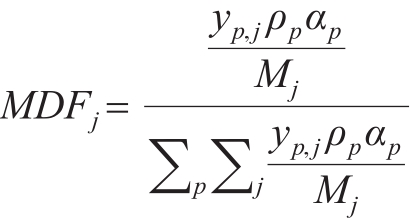
when p, j represents phase and component number, y,  ,
,  and M represents mass fraction, density, volume fraction and molar mass respectively. The advantage in using this quantity for the analysis is that it clearly shows the region of liquid and vapor cloud concentration, as shown in Figure 8 and Figure 9 respectively.
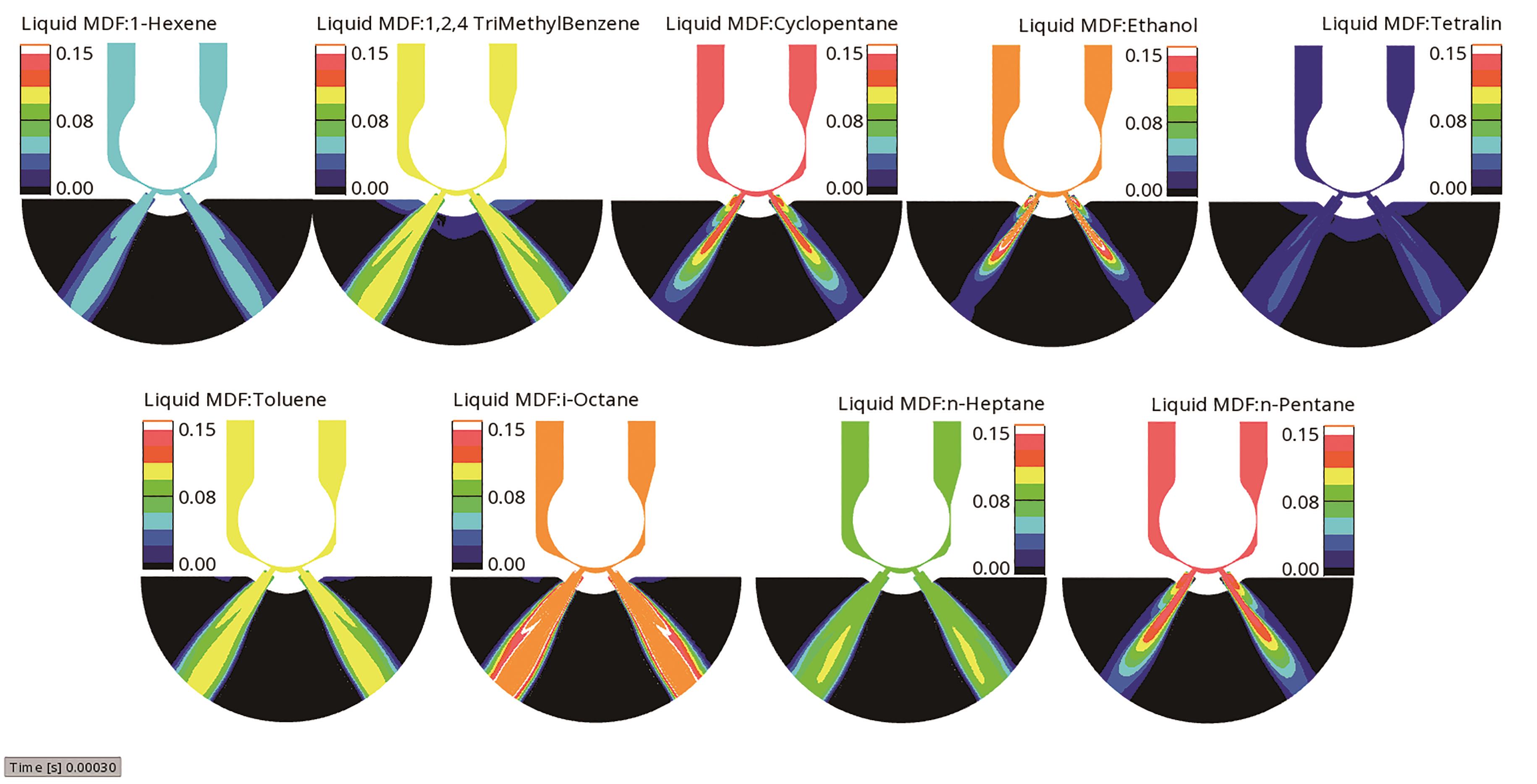
Figure 8. Molar density fraction of individual components (or species) in the liquid composition at 0.3 ms after Start of Injection (SOI).
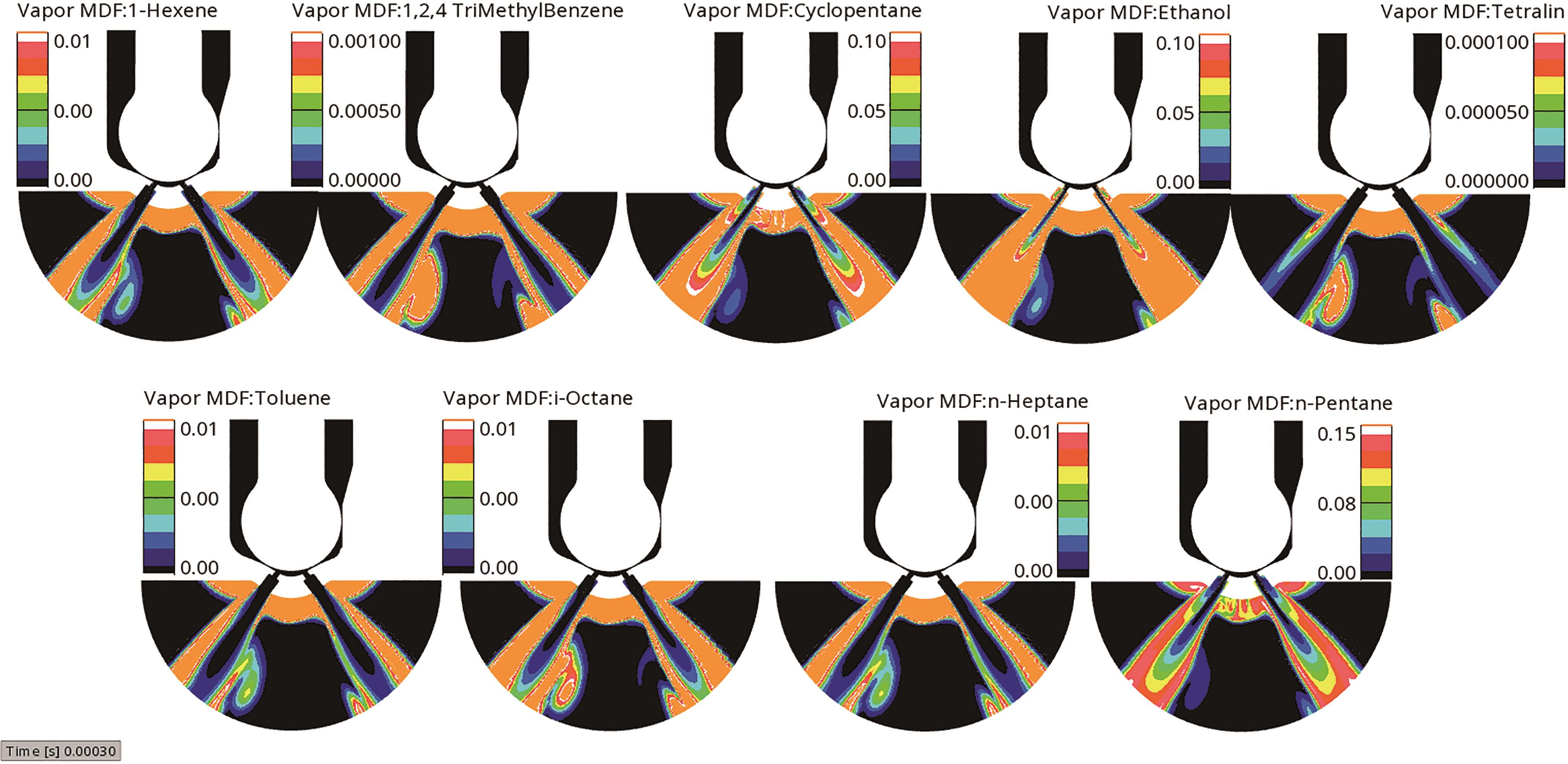
Figure 9. Development of molar density fraction of individual components (or species) in the vapor composition at 0.3ms after Start of Injection (SOI).
Flashing of a multi-component mixture strictly depends on the volatility of each component. In the analyzed PACE fuel*, ethanol is the lightest component while 1,2,4-trimethylbenzene and tetralin are the heaviest. According to the flash boiling physics these accounts to faster vaporization of ethanol and slower vaporization of 1,2,4-trimethylbenzene and tetralin. From Figure 8 and Figure 9 this is clearly visible such that rate of vaporization of other components is between the rate of vaporization of ethanol and 1,2,4-trimethylbenzene.
6. Validation with Experiment
In order to validate the multi-component model, the results from Argonne National Laboratory (ANL*) are considered. Figure 10 shows the qualitative comparison of liquid density (μg/mm 3) at a plane 1mm from the nozzle tip. It is observed that the results from both AVL FIRETM M simulation and ANL experiments* show good agreement. In both cases, for each spray cone, there exists an intact liquid core on the inner side and getting diffused along the radial direction.

Figure 10. Qualitative comparison of liquid density (μg/mm3) at a plane 1mm from the nozzle tip between ANL Experiment* and AVL FIRE™ M simulation.
Quantitative comparison of integrated liquid density, area density (μg/mm2) projected over the central line in a plane ( Figure 10) 1mm from the nozzle tip between ANL Experiment* and AVL FIRETM M simulation is presented in Figure 11. Each point in this graph is the integrated value of liquid density, area density, over a line in the plane as shown in Figure 10 at different locations at the central line. AVL FIRETM M simulation and ANL Experiment show good agreement.
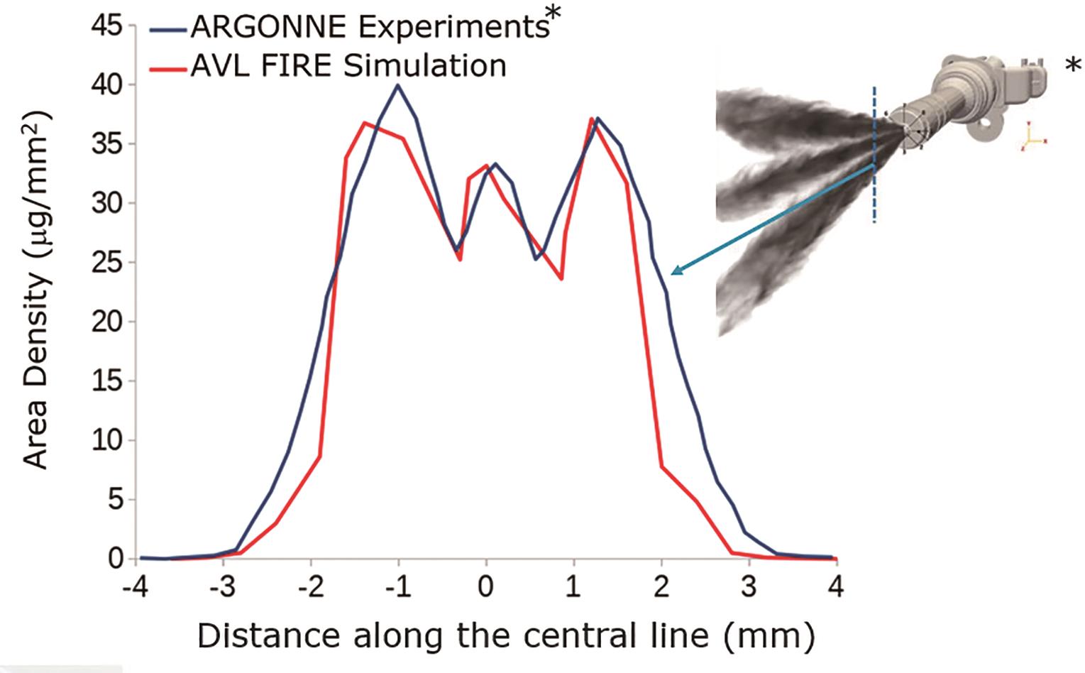
Figure 11. Quantitative comparison of integrated liquid density, area density (μg/mm2) projected over the central line in a plane (Figure 10) 1 mm from the nozzle tip between ANL Experiment* and AVL FIRETM M simulation.
7. Influence of Multi-Component Nozzle Flow Simulation on Multi-Component Engine Simulation
The behavior of liquid jet and its disintegration drastically changes during flashing evaporation. This in turn has serious implications on spray dispersion and wall impingement which will affect the combustion quality and pollutants amount. Initializing the engine spray using nozzle files from internal nozzle flow simulations is an inevitable step. In the engine simulations, the fuel injected quantity and injection timing is calibrated with respect to the engine operating conditions. Figure 12 shows the mass fraction of species at 425 crank angle degrees (during the fuel injection period). As observed in nozzle flow simulation, engine simulation also shows similar vaporization behavior such that ethanol is vaporizing faster compared to 1,2,4-trimethylbenzene and tetralin. Another significant point to notice here is that heavier components are more susceptible for wetting which in turn is the main contributor of soot during combustion.
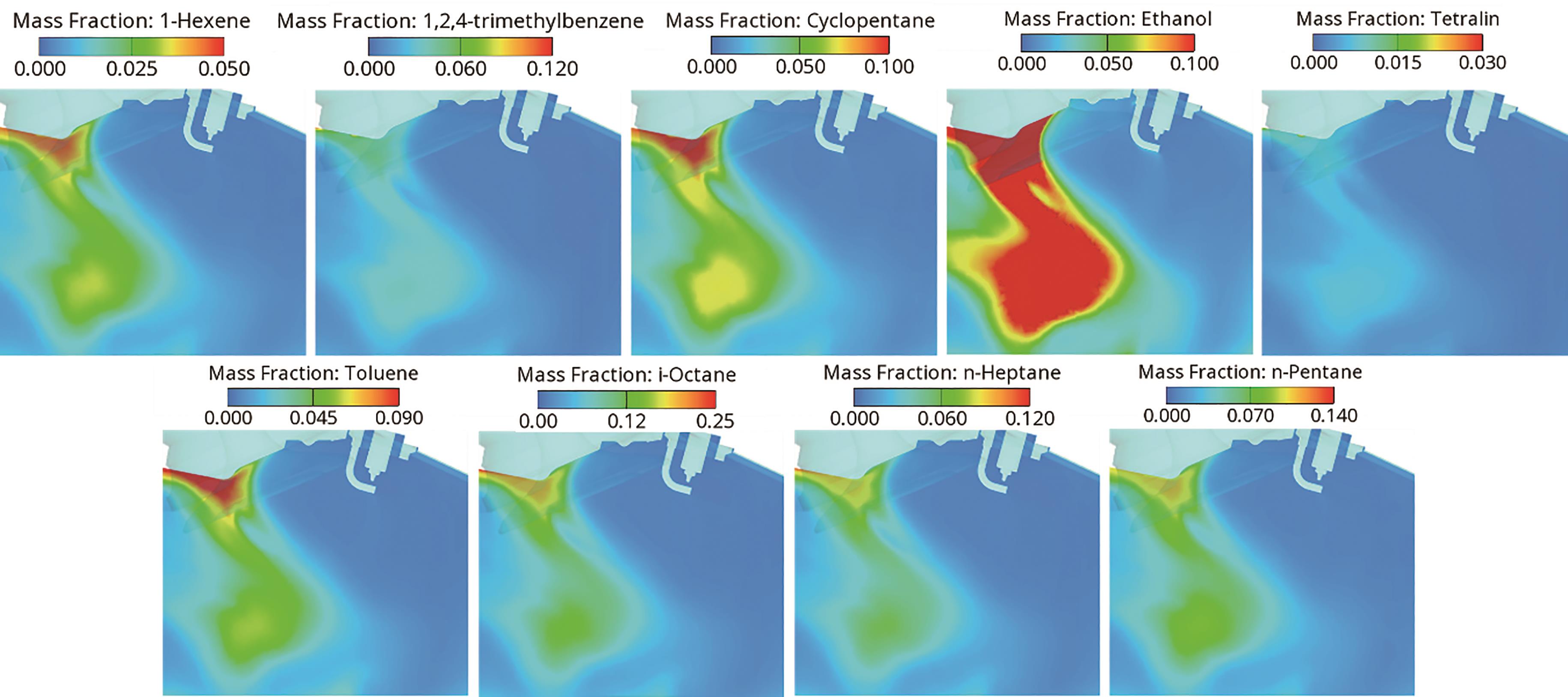
Figure 12. Development of mass fraction of species during the injection period in engine simulation at 425 Crank angle degrees.
It is also important to check how this multi-component spray at flash boiling condition is affecting the combustion and emissions. Figure 13 shows the key combustion and emission variables at 720 crank angle degrees.
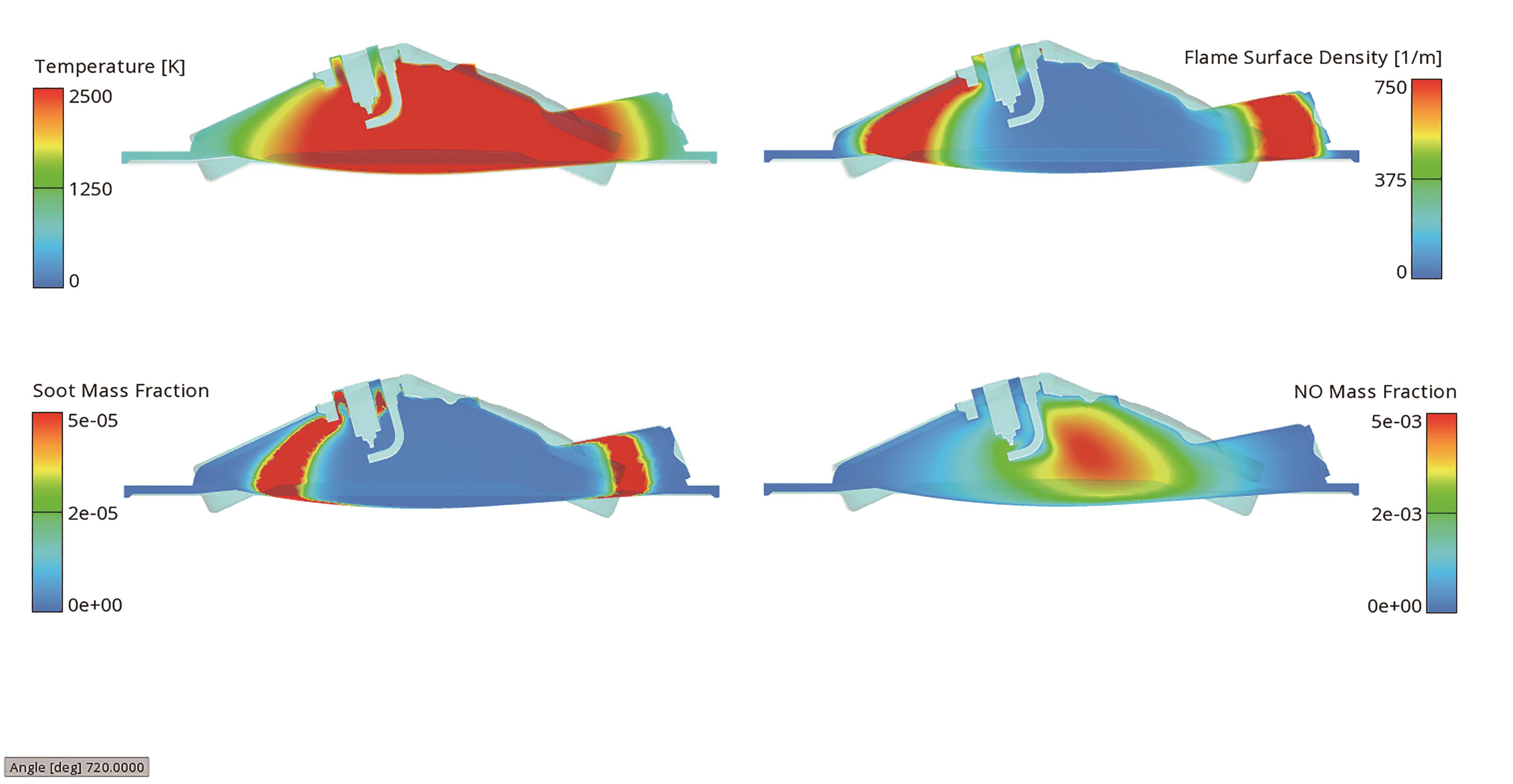
Figure 13. Qualitative analysis of combustion variables and pollutants amount at 720 Crank angle degrees.
8. Conclusion
In summary, this article provides a complete virtual solution and workflow from nozzle flow simulation to in-cylinder simulation using a multi-component fuel. The comparison of results of multi-component spray simulation with respect to experiments shows good agreement. Different component developing process could be detailed considered as well as the distribution and developing process of different components and phases in engine cylinder under flash boiling condition. This provides a practical method to have better understanding of the in-cylinder process and guide the development of engine combustion system.
Author Contributions: Conceptualization, B.M.D.; methodology, B.M.D. and Y.Z.; validation, B.M.D.; formal analysis, B.M.D.; investigation, B.M.D.; data curation, B.M.D., Y.Z. and E.Z.; writing—original draft preparation, B.M.D.; writing—review and editing, B.M.D., Y.Z. E.Z. and L.Z.; visualization, B.M.D., Y.Z. and E.Z.; supervision, B.M.D. All authors have read and agreed to the published version of the manuscript.
Funding: This research received no external funding.
Data Availability Statement: Not applicable.
Conflicts of Interest: The authors declare no conflict of interest.
References
- Zuo, B.; Gomes, A.M.; Rutland, C.J. Modeling superheated fuel sprays and vaporization. International Journal of Engine Research 2000, 1(4), 321–336. DOI: https://doi.org/10.1243/1468087001545218
- Zhao, F.; Lai, M.C.; Harrington, D.L. Automotive Spark-ignited Direct injection Gasoline Engines. Progress in Energy and Combustion Science 1999, 25(5), 437–562. doi: 10.1016/S0360-1285(99)00004-0. DOI: https://doi.org/10.1016/S0360-1285(99)00004-0
- Drake, M.C.; Fansler, T.D.; Lippert, A.M. Stratified-charge Combustion: Modeling and Imaging of a Spray-guided Direct-injection Spark-ignition Engine. Proceedings of the Combustion Institute 2005, 30(2), 2683–2691. doi:10.1016/j.proci.2004.07.028 DOI: https://doi.org/10.1016/j.proci.2004.07.028
- Xu, M.; Zhang, Y.; Zeng, W.; et al. Flash boiling: Easy and better way to generate ideal sprays than the high injection pressure. SAE International Journal of Fuels and Lubricants 2013, 6(1), 137–148. DOI: https://doi.org/10.4271/2013-01-1614
- Zhang, G.; Xu, M.; Zhang, Y.; et al. Characteristics of flash boiling fuel sprays from three types of injector for spark ignition direct injection (SIDI) engines. In Proceedings of FISITA 2012 World Automotive Congress. Lecture Notes in Electrical Engineering, vol. 189. Springer, Berlin, Heidelberg, Germany, 2013, pp. 443–454. DOI: https://doi.org/10.1007/978-3-642-33841-0_33
- Aleiferis, P.G.; Serras-Pereira, J.; Van Romunde, Z.; et al. Mechanisms of spray formation and combustion from a multi-hole injector with E85 and gasoline. Combustion and Flame 2010, 157(4), 735–756. DOI: https://doi.org/10.1016/j.combustflame.2009.12.019
- Li, Y.; Guo, H.; Ma, X.; et al. Morphology analysis on multi-jet flash-boiling sprays under wide ambient pressures. Fuel 2018, 211, 38–47. DOI: https://doi.org/10.1016/j.fuel.2017.08.082
- Arai, M.; Senda, J.; Xu, M. A consideration on Cavitation and Flash Boiling Atomization. 18th Annual Conference on Liquid Atomization and Spray System (ILASS-Asia), 2016.
- Devassy, B.M.; Petranovic, Z.; Edelbauer, W. Numerical Investigation and Experimental Comparison of ECN Spray G at Flash Boiling Conditions. SAE Technical Paper 2020, No. 2020-01-0827.
- AVL FIRE™ M, Graz (2023). https://www.avl.com/en-cn/simulation-solutions/software-offering/simulation-tools-z/avl-fire-m


